26
Exhibit V Operational description HO82WUALS13
ALS-1300 Technical and Operational Overview
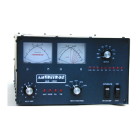
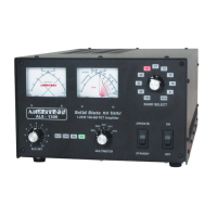
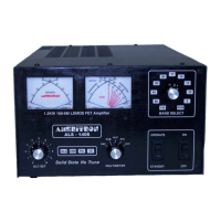
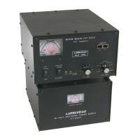
The ALS-1300 is an amateur radio multiband radio frequency linear power amplifier. This device requires
certification. This device complies with technical standards of CFR Title 47 part 97.317(a) and (b).
General Operation
This linear amplifier covers the 160, 80, 40, 30, 20, 17 and 15-meter amateur bands. Up to 100 watts exciter
power is applied to relay RLY1 on circuit board RLY. When power is on and the standby switch is in the
operate position, and when the rear panel RELAY control line is held low (below 1 volt), exciter power is
routed through RLY1 to the PD8 power divider board.
Power Division
The PD8 power divider board splits the signal path equally between two 600-watt power amplifier modules.
The PD8 circuit board consists of a conventional T power divider, components T2 and R7. This T splits the
signal into two equal level signals. Each signal path has a 5 dB attenuator consisting of high power resistors R1
through R6. The 5-dB attenuators on each output port terminate the T in 50 ohms and provide an additional 10
dB of input port isolation between the two PA modules. With a 50-ohm source, in excess of 30 dB port-to-port
isolation occurs between PA module inputs. A minimum of 16 dB isolation occurs regardless of input port
termination. The attenuators also work in concert with the magic-T to provide a 50-ohm input termination for
each PA module. The 50-ohm termination and input port isolation results in unconditionally stabile PA
modules.
PA Amplifiers
Power amplification comes from two 600-watt power amplifier modules. Each PA module (PAM-600) consists
of four MFR-150 field effect transistors. Each MRF-150 has between 200 mA to 400 mA quiescent current.
Transistor conduction angle is slightly over 180 degrees, providing linear class AB operation. The normal dc
drain operating voltage is approximately 50 volts with four FET’s per module in push-pull parallel. Both
modules employ significant negative feedback to improve linearity and stability. The FET’s have direct
resistive voltage feedback across each individual transistor from drain to gate, as well as push-pull transformer
(T2) coupled feedback common to the push-pull circuit. These feedback circuits improve gain flatness,
linearity, and stability. Push-pull operation, negative feedback, and linear biasing of FET’s provide significant
pre-filter harmonic suppression.
Cooling and Temperature
The four power FET’s in each module mount on a forced-air cooled aluminum heatsink. Four dc fans cool the
heatsink. Two thermistors (R1 heatsink, R2 transistor) sense the temperature of the power amplifier transistors
and their heat sinks. Transistor temperature sensor R2 regulates bias voltage, reducing bias voltage when



 To Next Page