Do you have a question about the AMERITRON ALS-1306 and is the answer not in the manual?
Guide for optimal placement of the amplifier and power supply units.
Instructions for connecting the power supply to the mains.
Explains warning lights and fault codes for diagnosing operational issues.
Pre-operation checks and considerations for safe and correct use.
Specifications for mains voltage, frequency, and fuse requirements.
Highlights of the switching power supply's capabilities and design.
Guidance on selecting a suitable and safe location for the power supply unit.
Interprets warning lights and fault codes for diagnosing operational issues.
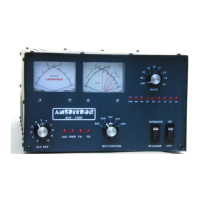
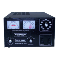
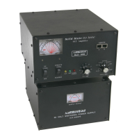
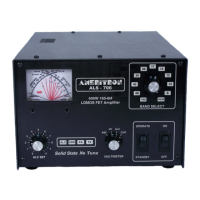
General description of the ALS-1306 amplifier's capabilities and design.
Recommended space around the amplifier for proper ventilation and access.
Important safety and operational warnings related to installation.
Step-by-step guide for connecting the amplifier's power and signal cables.
Guidelines for electrical grounding to ensure safety and prevent lightning damage.
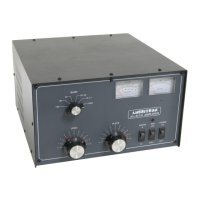
Description of various connectors on the amplifier's rear panel including power, ALC, relay, RF, and interface ports.
Details on RJ45 connectors for remote control and interface boxes.
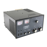
Explanation of meters for current, power, and SWR, plus status LEDs.
Description of knobs and switches for band selection, ALC, and mode operation.
Table detailing band frequency ranges and automatic disable points.
Precautions for using the amplifier with MARS or CAP frequencies.
Explanation of front panel warning lights and their meanings for fault diagnosis.
Table detailing faults, causes, and cures based on warning lights.
Overview of the amplifier's band coverage and basic operating principles.
Description of how the signal is split between power amplifier modules.
Details on the power amplifier modules and their components.
Explanation of the 2KWF6 low-pass filter circuit and its function.
Overview of the CB2 control board's logic and protection features.
Description of the SWR board and its measurement function.
Descriptions of 2KWF6, RLY, BS2, MB1, and RJ45 boards.
Overviews of CB2, PA Boards, and PD8 boards.
Description of the SWR sensor board.
