Revision 2
17
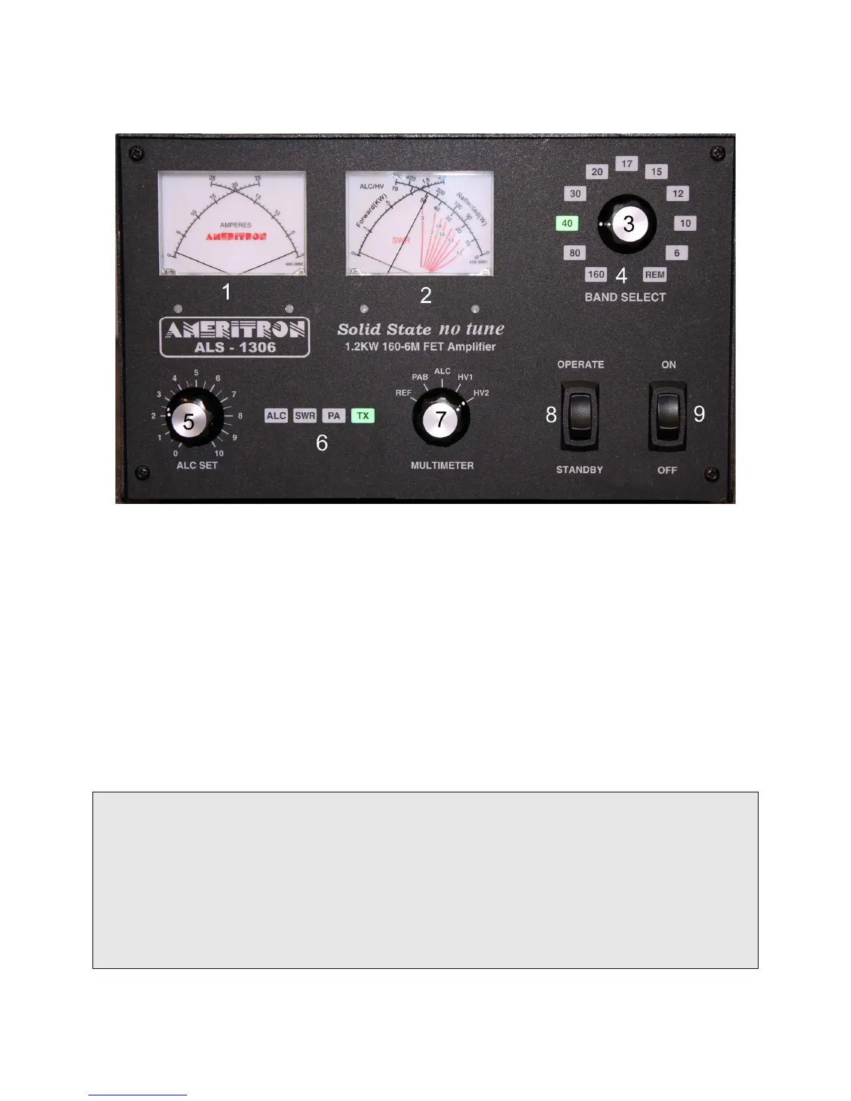
Front Panel
Amplifier Front Figure 2
The front panel contains the following indicators and controls. To prevent damage, become familiar with
the front panel before operating the amplifier.
1 FET module current meters
2 Forward Power meter and Multimeter (reflected power, module RF balance, ALC,
and Module supply voltages) selected by knob 7.
3 Band or REMote selector knob.
4 Backlit Band or REMote LED indicators.
5 ALC limit adjustment.
6 Backlit Function and Fault Warning LED indicators.
7 Meter 2 multimeter scale function selector knob.
8 Operate and Standby switch, also resets fault warnings.
9 Main Power, also resets power supply overload.
Note: The right-hand meter’s left scale-arc (fig.2 ref 2A) continuously indicates forward peak envelope
power (PEP) output directly in kilowatts. It is 100 watts, or 0.1 kW, per meter scale picket. PEP has no
fixed relationship to long-term average power except, for constant amplitude carriers like a steady CW
carrier, when PEP and average powers are equal. PEP is the highest average power during one (or more)
radio frequency cycle(s) at the modulation envelope crest.
The right-hand meter’s rightmost scale-arc is used for PEP reflected power in watts and combiner
imbalance on the upper scale numbers and pickets. Notice power meter calibrations are not evenly
spaced. Lower scale numbers and pickets are evenly spaced, and are for other functions. The lower right
scale is used for relative ALC setting and power amplifier modules HV (0-70 volts).