Revision 2
10
General Information
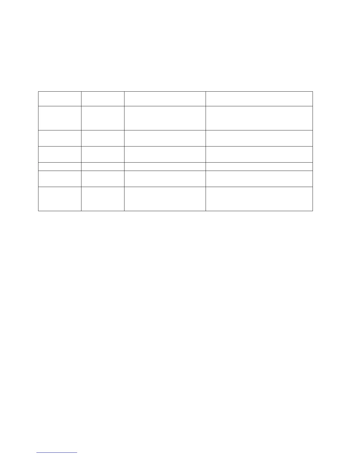
Alert Codes
The SWR, PA, TX lamps, and band switch lamps indicate operational faults. Operational faults
reset by placing the amplifier in standby. The following table applies to faults:
Warning
light Steady
Warning
light Flash
Fault Cause or Cure
SWR TX
Antenna Reflected
Power
High antenna SWR or
intermittent antenna or feed line
connection
SWR, PA Band
Wrong filter Exciter or amplifier on
incompatible band, filter failure
PA TX
PA FET too hot Excessive power for duty cycle
or SWR, lack of proper airflow
PA Combiner unbalance
10M, PA,
TX
Illegal 11 meter Excessive 27 MHz signal level
REM, PA
No or wrong band when
on remote
Defective or improper remote
cable, or bad radio band data
information
Amplifier Overview
The Ameritron ALS-1306 is a solid-state, 1200-watt nominal RF output power, 1.8-54 MHz
amplifier. The ALS-1306 meets or exceeds all FCC requirements governing amateur radio
external power amplifiers.
The ALS-1306 uses four pairs of exceptionally low distortion, push-pull MRF-150 (or
equivalent) SSB RF power transistors. The characteristics of linear high-voltage FETs are very
much like those of triode vacuum tubes. While this amplifier will run more than 1200 watts PEP
output, linearity might suffer. Ameritron recommends running 1200 watts or less peak power for
maximum linearity. If these instructions are followed this amplifier will have comparable IM
performance to the best vacuum tube linear amplifiers.
Temperature sensors on each PA (power amplifier) module monitor heat. Bias and fan speed
track FET temperature. The ALS-1306 protection circuitry reduces power as transistors approach
conservative thermal limits, and disables the amplifier before transistor exceed safe operating
temperature limits.
Harmonic suppression comes from push-pull operation of linear devices, followed by high-
quality 5-pole low-pass filters. Many amplifiers use inexpensive ceramic disc or mica capacitors.
Lead inductance of mica or disc capacitors reduces high-order harmonic suppression. This
amplifier uses quality multi-layer high voltage chip capacitors.
This amplifier greatly exceeds FCC harmonic requirements. HF harmonic suppression typically
10-15 times better than FCC mandated suppression levels. Harmonics are practically
immeasurable on all television channels. An external low-pass filter has minimal effect with this
amplifier.
Antenna switching is through a pair of sequenced miniature relays on a plug-in module. This
facilitates relay servicing or maintenance. Relay switching time is approximately five