EasyManua.ls Logo

AMERITRON Al-800H User Manual

AMERITRON Al-800H
39 pages
To Next Page IconTo Next Page
Page #1 background imageLoading...
Page #1 background image
AL-800H Instruction Manual
i
WARNING!!
NEVER APPLY POWER TO THIS AMPLIFIER WITH THE COVER REMOVED!
CONTACT WITH THE VOLTAGES INSIDE THIS AMPLIFIER CAN BE FATAL!
PLEASE READ THIS MANUAL BEFORE ATTEMPING TO OPERATE
EQUIPMENT! Improper or abusive operation of this amplifier can damage the tubes
or other components in this amplifier. Damage caused by improper or abusive
operation is not covered under the warranty policy.

Table of Contents

Question and Answer IconNeed help?

Do you have a question about the AMERITRON Al-800H and is the answer not in the manual?

AMERITRON Al-800H Specifications

General IconGeneral
TypeLinear Amplifier
TuningAutomatic
Input Impedance50 Ohms
Tube3-500ZG
Output Impedance50 Ohms
ALCYes
CoolingForced Air
Gain12 dB
Power Output800 Watts PEP

Summary

Unpacking Instructions

Features

AL-800H Technical Specifications

General Information

Safety Interlock

Interlock switch preventing operation when cover is removed.

Timer - Overload Circuits

Grid Overload Protection

Electronic circuit protecting grid from excessive current.

Thermal Overload

Sensor disabling transmitter if transformer overheats.

Cathode Warm-up Timer

Circuit ensuring tubes reach operating temperature before use.

Power Supply

Heater Supply

Circuit satisfying tube manufacturer's heater requirements.

Plate (HV) Supply

Full wave doubler circuit with heavy-duty transformer.

Meters

Current Meter (plate and grid)

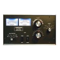
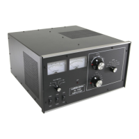
Meter indicating plate and grid current on front panel.

Multimeter

Multimeter Functions

Switch selecting HV, REF, ALC, and ALC SET measurements.

Peak Envelope Power vs. Average Power

Tube Life

Export Modifications

Technical Assistance

Installation Guidelines and Suggestions

Location Of The Amplifier

Proper placement for airflow and unobstructed operation.

Ventilation

System designed to maintain safe tube temperatures.

Power Connections

Guidelines for connecting to AC power sources.

Grounding

Transformer Connections

Jumper Connections

Chart for setting transformer primary jumpers for line voltage.

Interconnections

Operating Instructions And Guidelines

Front Panel Controls

Explanation of front panel switches and knobs.

ALC Metering, Controls, and Adjustments

ALC Metering Functions

How the multimeter displays ALC voltage and grid current.

ALC Controls

Adjusting grid current for ALC action.

ALC Adjustments

Fine-tuning ALC for optimal signal quality and linearity.

Rear-Panel "ALC LIMIT" Control

Limits maximum ALC voltage to match exciter requirements.

ALC Limit Adjustment (rear panel)

Procedure to correct "pumping" from ALC sensitivity.

Driving Power

Tube and Component Life

Tuning

Tuning Procedure

Step-by-step guide for proper amplifier tuning.

ALC SET Control

Additional SSB Notes

AM (Amplitude Modulation) Operation

FM (Frequency Modulation), RTTY, and Digital Operation

Audio Distortion

QSK Operation

Periodic Maintenance

Parts List

Power Supply / SWR Board (50-0800H-1)

List of components for the power supply board.

Tuned Input Board (50-0800H-2)

List of components for the tuned input board.

Meter Board (50-0800-3)

List of components for the meter board.

Timer / Overload Board (50-0117-2)

List of components for the timer/overload board.

AL-800H Main Chassis Parts List

List of major chassis components and assemblies.

Frequency Coverage

Amplifier Tuning Log

Schematics

Wiring Diagram

Schematic illustrating the amplifier's internal wiring connections.

Related product manuals