Do you have a question about the AMERITRON AL-811HX and is the answer not in the manual?
The AL-811H is a grounded grid linear amplifier designed for amateur radio use, operating in class AB2 for both Single Sideband (SSB) and Continuous Wave (CW) modes. It utilizes low-cost 811A power triodes to achieve its amplification function.
The primary function of the AL-811H is to amplify RF signals from a transmitter or transceiver, providing higher output power for improved communication range and signal strength. It achieves this by taking a relatively low-power RF input and boosting it to a significantly higher power level. The amplifier is designed to operate with exciters that have an RF output of approximately 70 watts, though it can be used with lower output exciters, albeit with reduced amplification. The AL-811H includes a safety interlock system that disconnects AC input power from the transformer when the top cover is removed, preventing accidental contact with high voltages. However, it's crucial to note that the filter capacitors may retain a charge, so users are advised to allow them to discharge before touching internal components.
The power supply incorporates a combination plate, filament, and control transformer with a "buck-boost" winding. This unique feature allows for primary voltage adjustments to match a wide range of line voltages, typically centered around 110 and 230 volts. This versatility ensures optimal voltages for the tubes and other components, contributing to maximum performance and extended component life. The filament circuit is designed to meet the tube manufacturer's requirements for tube performance and longevity, controlling inrush current through the transformer's internal resistance and impedance, filament choke resistance, and filament wiring resistance.
An Automatic Level Control (ALC) circuit is integrated to prevent over-driving the amplifier. It converts a portion of the RF drive voltage at the exciter end of the tuned input circuit into a negative control voltage. This voltage is then used to limit the exciter drive to safe levels, particularly for exciters producing more than 70 watts of output power. The ALC circuit can be adjusted to ensure optimal performance across different bands, though a compromise in adjustment may be necessary for consistent performance.
The amplifier also features a neutralization circuit, which helps reduce unwanted feedback, thereby improving overall performance and stability. For keying, the AL-811H uses a relay that keys the amplifier when grounded, sourcing +12 VDC open circuit and supplying 100mA when grounded. A built-in pulse-canceling diode protects the exciter from back-pulse.
The AL-811H offers several features designed to enhance user experience and operational reliability. One notable feature is its "Fast Warm Up Time," with the 811A tubes requiring approximately 10 seconds to warm up before operation. This allows for quick deployment. The 811A tubes themselves are described as "Long Tube Life," being reliable transmitting tubes capable of rugged operation even in demanding modes like RTTY and SSTV.
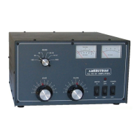
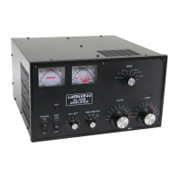
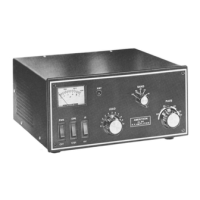
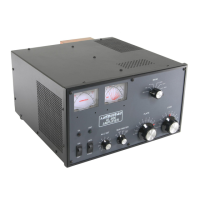
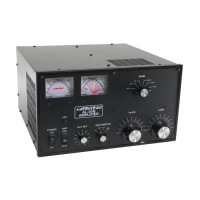
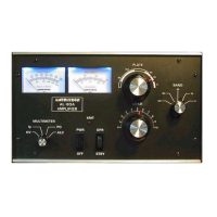
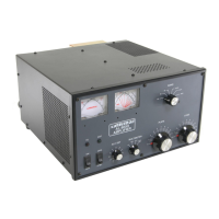
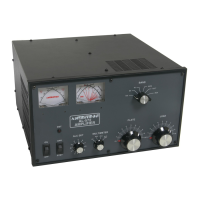
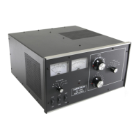
A "Tuned Input" circuit, specifically a Pi-Network with slug-tuned coils, matches the 811A tubes to 50-ohm exciters, ensuring efficient power transfer. The amplifier is equipped with "Two Illuminated Panel Meters." The right meter continuously displays the 811A grid current, which is crucial for proper loading. The left meter can be switched to display either the High Voltage (HV) or Plate Current (Ip), providing comprehensive monitoring of the amplifier's operational status.
"Vernier Plate and Load Adjustments" are provided for precise tuning. Both tuning controls feature 6:1 reduction drives, allowing for smooth adjustments and accurate logging scales, which facilitates rapid tune-up. An "Operate/Standby Switch" allows users to remove the amplifier from the RF line while maintaining filament and plate voltages, enabling "barefoot" operation without having to power down the entire unit. An "XMT Indicator LED" on the front panel provides a visual confirmation of proper amplifier keying by the exciter.
For export models, a simple modification allows operation on frequencies above 15 meters, expanding the amplifier's utility for international users. These models are shipped with the modification already in place and are pre-wired for 240V operation, supplied with 8 ampere fuses. Domestic models are typically wired for 120V operation and supplied with 12 ampere fuses.
Maintenance of the AL-811H primarily involves ensuring proper ventilation, grounding, and periodic cleaning, as well as careful handling of the tubes.
For "Ventilation," it is critical not to block or restrict the ventilation holes in the cover, as the system is designed to maintain safe 811A tube temperatures during operation. Users are advised against "assisting" the air flow unless an external fan significantly exceeds the amplifier's fan CFM, and not to mount additional fans on the cabinet. Heat-sensitive objects should be kept clear of the exhaust air stream, which can become warm at high power levels.
"Grounding" is emphasized as a crucial maintenance step. Users should connect a good earth or water pipe ground to the ground post on the rear panel, using the heaviest and shortest connection possible, preferably solid copper. If a water pipe ground is used, it's important to inspect connections around the water meter for any plastic or rubber hose segments that could interrupt electrical continuity, and install jumpers if necessary. All equipment at the operating position should ideally be grounded to a common point.
Regarding "Power Connections," the AL-811H is supplied with a NEMA 5-15P plug for 120V operation. If rewiring for 240V, the fuses must be changed from 12 ampere to 8 ampere. It is explicitly stated that operation at 240V is not required to improve performance. The manual provides a diagram for proper wiring for various line voltages and warns against rewiring the power supply to boost high voltage above 1800 volts or attempting to rewire the amplifier while it is connected to power. The wiring between the fuse box and the AC outlet must be 14 gauge or larger to handle the operating current without significant voltage drop.
"Periodic Maintenance" includes inspecting and cleaning high voltage areas, particularly the plate choke and air variable capacitors, which can attract dust and dirt. These areas should be inspected every few months, especially if the amplifier is operated in a dusty environment. Before any service work, the line cord must be unplugged, and at least 90 seconds allowed for the power supply capacitors to discharge. A safety wire must be installed from ground to the anode connection of the tubes before beginning service work and removed afterward. A soft bristle brush dipped in alcohol can be used to clean these areas.
The manual also provides detailed instructions for "Unpacking," including carefully lifting the amplifier, inspecting for shipping damage, and saving packing materials. It guides users on removing the cover, locating and installing fuses (noting different fuse requirements for 120V and 240V operation), and carefully removing foam packing material around the tubes. Instructions for installing the 811A tubes emphasize aligning large diameter pins with holes, applying gentle force, and avoiding excessive rocking or twisting. It also describes a safe method for removing the ceramic anode connector from the tubes if necessary, involving a twisting and spinning pulling motion while holding the connector firmly. Finally, it advises on reinstalling the cover, starting with the back screws and tightening all screws only after they are in place.
| Power Output | 800 watts PEP |
|---|---|
| Input Impedance | 50 ohms |
| Output Impedance | 50 ohms |
| ALC | Yes |
| Power Supply | 120/240VAC |
| Cooling | Fan |
| Frequency Coverage | 160-10 meters |
| Tubes | 4 x 811A |