Do you have a question about the AMERITRON AL-80A and is the answer not in the manual?
Explains readings for Plate Voltage (HV), Plate Current (Ip), and Peak RF Watts (PO).
Describes the ALC meter's indication of relative drive level.
Provides typical settings for plate and load controls across various bands.
Details the frequency ranges covered by the AL-80A and AL-80AX models.
Detailed circuit schematic of the AL-80A amplifier.
Chart showing input/output settings for various bands.
Comprehensive list of components used in the AL-80A.
Details input circuit type, VSWR, and drive power requirements.
Details output circuit type and power ratings for various modes.
Details power supply circuit, voltages, current, and transformer specs.
Guidance on carefully removing the amplifier from its packaging.
Steps for safely installing the 3-500Z tube and plate cap.
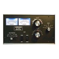
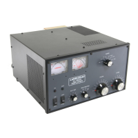
The Ameritron AL-80A is a high-power linear amplifier designed for amateur radio use, offering over 1000 Watts output SSB PEP (Peak Envelope Power) and 850 Watts output on CW (Continuous Wave). It is engineered for high efficiency and reliability, covering amateur radio bands from 160 through 15 meters. Additionally, it provides wide frequency coverage for MARS (Military Auxiliary Radio System) and other authorized services requiring high-power operation.
The AL-80A utilizes an Eimac 3-500Z high-mu triode in a class AB₂ grounded grid circuit. Its primary function is to amplify the RF signal from a transmitter or transceiver, boosting its power output for long-distance communication. A key feature is the built-in Automatic Level Control (ALC) circuit, which prevents the amplifier output from "flat-topping" – a form of distortion that occurs if the exciter gain is inadvertently set too high. This ALC circuit ensures a clean output signal by automatically reducing the drive level when necessary.
Ventilation: The AL-80A's ventilation system is designed to maintain safe tube seal temperatures. Users must ensure ventilation holes are not blocked, avoid "assisting" airflow unless the fan used exceeds the AL-80A blower CFM by a factor of 2:1, and not mount additional fans on the cabinet. Heat-sensitive objects should be kept clear of the exhaust air stream, which can become quite warm at high power levels.
Power Connections: The amplifier is factory wired for 117V, 50/60 Hz primary line voltage and comes with a NEMA 5-15P plug. It can be modified for 234 VAC operation by moving two jumper wires on the terminal block located on the left side of the rear panel. The wiring between the fuse box and the amplifier A.C. outlet must be No. 12 gauge or larger to supply the required 15 amperes without significant line voltage drop. The 117V outlet should be fused for 20 amperes.
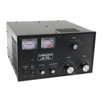
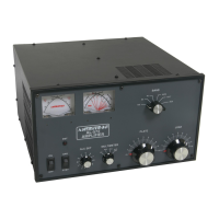
Metering Functions: The AL-80A features two illuminated panel meters. The Grid Current meter provides a continuous reading, an exclusive Ameritron feature, indicating proper amplifier operation (not to exceed 200 mA). The other meter reads Plate Voltage (HV) on a 0-3500 Volt scale (100 volts per division), Plate Current (Ip) on a 0-700 mA scale (20 mA per division), Peak R.F. Watts (PO) on a 0-2000 scale (50 watt divisions below 1000 watts, 100 watt divisions above 1000 watts), and ALC detector voltage (relative drive level indication, 200 watts full scale).
ALC Adjustment: A shielded audio-type cable connects the 0-20 volt negative ALC voltage to the transmitter ALC input. The amplifier must be properly tuned on CW before adjusting the ALC. Adjustment involves setting the multimeter to PO, increasing transmitter audio, speaking into the microphone, and adjusting the ALC ADJ control on the rear panel until the amplifier is not clipping on an RF scope or audio peaks do not exceed single tone output of 1000 watts.
Tuning Instructions: A detailed step-by-step tuning procedure is provided, starting with setting front panel switches (PWR to OFF, OPR to STBY, MULTIMETER to HV), plugging in the A.C. line cord, setting PWR to PWR (meter lamps should light, blower should start, HV should read 3100V nominal), tuning the exciter into a 50 ohm load with drive down, setting bandswitch and tuning controls, placing MULTIMETER to Ip (should read zero), and then placing STBY-OPR to OPR. The process continues with applying drive to achieve specific grid and plate current readings, adjusting LOAD and PLATE for maximum output, and finally optimizing for 1000 watts output or 200 mA grid current. For CW, drive power should be reduced to 400 mA plate current or less. For SSB, modulation crest should not exceed 400 mA plate current, 100 mA grid current, or 1200 watts PEP output. A tuning chart provides typical settings for frequency, bandswitch, plate control, and load control.
Installation: Connect the RF output of the transmitter to the RF IN connector on the AL-80A with 50 ohm coax. Connect the antenna system to the RF OUT connector with RG-8 type coax. Connect the RELAY phono jack on the AL-80A to the normally open terminals of the RELAY jack on the transmitter. The RELAY jack provides positive 12 VDC open circuit and 100 MA when pulled to ground. A short ground lead from a good earth ground to the GND terminal is recommended. A 12V connection on the rear panel provides 12 VDC at 100 MA maximum for external dial lamps or accessories.
Unpacking and Tube Installation: Instructions are provided for carefully lifting the amplifier out of its packing material, examining for damage, and notifying the transportation company if any is found. The cover is removed by Phillips screws, and packing material from the plate cap assembly is removed. The 3-500Z tube is inserted into the socket, and the plate cap connector is secured with a screw, ensuring the solder lug is on the underside. The instructions emphasize not to overtighten the screw.
Warranty and Modifications: The manual explicitly states: "Do not make any modifications to the AL-80A circuit before checking with our engineering staff. Improper changes may damage the AL-80A and void the warranty."
Packing for Service: Users are advised to save all hardware and packing materials in case the unit needs to be returned for factory service. Units returned without proper packing may be damaged, and shipping claims cannot be made. Crucially, the amplifier should never be shipped with the tube installed.