93050-OLV Division 2 Sample System
Figure 2A: SS-4-20mA Out-
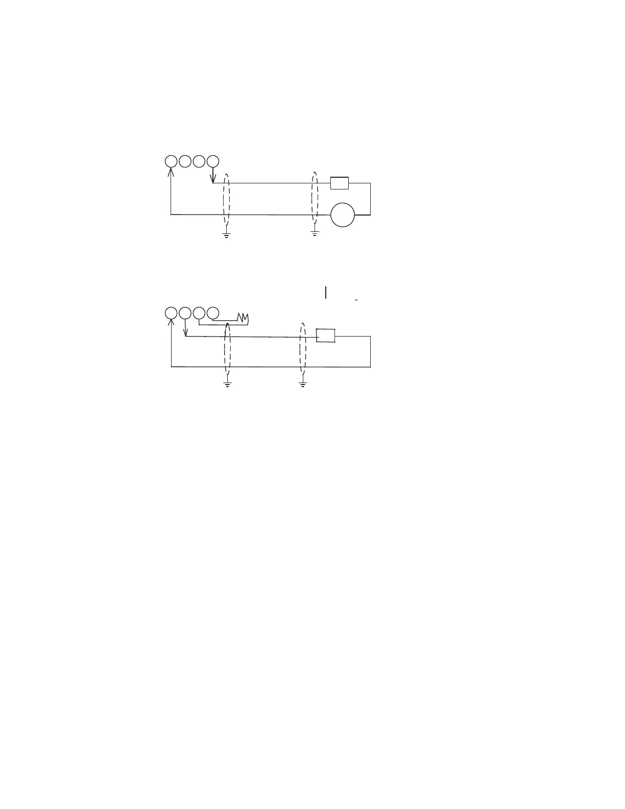
4-20 mA Output, Loop Powered (TB-3) See Note 6
3 4 5 6
3 4 5 6
4-20 mA Output, Self Powered (TB-3) See Note 7
R
Load
+ -
External 24V DC
Supply
+
-
R
Load
+
-
4-20 mA Output, Wiring
Notes
1.
Cable should be shielded with single twisted
pair.
2. Cable shields should be connected to both the analyzer and the DCS. If this is not
possible, cable shields should be tied to the chassis at each 3050-OLV. If this is not
possible, tie the shield at the PC or DCS to chassis and remaining shield to the chassis
through a 0.1 mF @ 500V capacitor.
100 to 300 Ohm
100 Ohm
100 to 400 Ohm
3. e 3050 signal common is connected to earth ground. If the analog output is also
grounded, the analog output will no longer be electrically isolated. Contact AMETEK if
this situation occurs.
Ω4. Analyzer power must be removed when connecting or disconnecting the 4-20 mA signal.
5. e 4-20 mA loop circuit must have a load resistance of between 100 and 500 ohms or
malfunction may occur (Max 100 ohms when local 4-20 ma display is present). If a loop check is
performed, a 100 ohm resistor must be placed in series with the ammeter.
6. In Loop Powered mode, remove factory installed 100 Ω resistor at TB3-5 to TB3-6
and jumper at TB3-3 to TB3-4.
7. In Self Powered mode when the optional local 4-20 ma display is present and no remote device is in use,
the circuit must be completed with factory installed jumper from TB3-3 to TB3-4 and an additional
100 Ω resistor from TB3-5 to TB3-6.
 Loading...


