EasyManua.ls Logo

Ametek 3050-DO

Ametek 3050-DO
83 pages
To Next Page IconTo Next Page
Loading...
3050-DO Moisture Analyzer
USER MANUAL
PN 305725901, Rev YF
AMETEK 3050 Congurator Software Version 2.20

Table of Contents

Question and Answer IconNeed help?

Do you have a question about the Ametek 3050-DO and is the answer not in the manual?

Ametek 3050-DO Specifications

General IconGeneral
Output4-20 mA, RS-232
Operating Temperature0 to 50°C
TypeOxygen Analyzer
Resolution0.01 mg/L
Power Supply115/230 VAC, 50/60 Hz
Humidity Range0 to 95% RH (non-condensing)
Enclosure RatingNEMA 4X (IP66)

Summary

Safety Notes

Electrical Safety

Safety precautions for electrical connections and grounding.

Grounding

Mandatory instrument grounding for performance and safety.

Personnel and Equipment Safety Information

Do Not Operate without Covers

Warning against operating the product with covers or panels removed.

Use Caution When Lifting

Advice to use caution when lifting the analyzer.

Use Proper Attire

Recommendation to wear protective gloves when handling hot equipment.

Use Proper Wiring

Using specified wiring to avoid fire hazards.

Avoid Electrical Overload

Warning against applying voltage outside specified terminal ranges.

Ground the Product

Follow grounding guidelines before making connections.

Overview

Controller Communication

Verification

Gas Flow

Internal Timing

3050-DO Analyzer Gas List

Installation and Start-Up

Safety Considerations

Review safety information before installation and powering up.

Pre-Installation Requirements

Personnel Technical Level Required for Installation

Required service personnel qualifications for installation.

Storage Prior to Installation

Recommended storage conditions to maintain warranty.

Analyzer Site Preparation

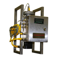
Guidelines for selecting an analyzer installation location.

Power Requirements

Information on power supply voltage and fusing.

System Tubing

Dry Reference Gas

Sample Gases

Sample Pressure and Temperature Requirements

Unpacking and Inspecting the Equipment

Tools, Equipment, and Supplies Required for Installation

Mechanical Installation

Optional Heated Pressure Reducer Installation

Electrical Connections in the Customer Connection Junction Box

4-20 mA Output Wiring

RS-232 Wiring

RS-485 Cables, Multiple 3050-DO Analyzers

RS-485 to RS-232 Conversion for Host PC

Analyzer Start-Up

Dry Down Period

Recommended duration for analyzer to dry down and stabilize.

Status LEDs and Alarms

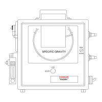
Explanation of LED indicators for system status.

Configuring the 3050-DO Analyzer for Remote Verification

ControllerInterface

AMETEK 3050 Analyzer Configurator Software

Software for setting up analyzer operating parameters.

Installing the Configurator Software

Step-by-step guide to install the configuration software.

Configuring the 3050-DO Analyzer

Working From the General Tab

Using the General tab to view config and define parameters.

PC Communications

Setup Configuration

Serial Numbers Information

Device Name and Description Fields

Save and Restore Configuration

Live Data Status

Status Display

Saving the Settings on the General Tab

PC Communications Setup Options

Communication Protocol Options

Options for AMETEK Serial, Modbus Serial, and Modbus TCP.

AMETEK Serial Setup

Initial PC communication setup using ASCII protocol.

Modbus Serial Setup

Setup for Modbus Serial communication after initial setup.

Modbus TCP Setup

Setup for Modbus TCP for remote communication.

AMETEK Serial Communication Setup

Port Selection

Selecting the COM port for analyzer connection.

Baud Rate Selection

Selecting the baud rate for data transfer.

RS-232 Port Configuration

For analyzers connected via RS-232 port.

RS-485 Port Configuration

For analyzers connected via RS-485 port.

Address Configuration

Network address for analyzer connection.

Modbus Serial Communication Setup

Port Selection

Selecting the COM port for analyzer connection.

Baud Rate Selection

Selecting the baud rate for data transfer.

Slave ID Configuration

Modbus slave address for the analyzer.

Time out Setting

Timeout value for establishing communication.

Stop Bits Setting

Number of stop bits for Modbus network.

Parity Setting

Parity setting for Modbus network.

Modbus TCP Communication Setup

IP Address Configuration

Unique network address for each analyzer.

Slave ID Configuration

Modbus slave address for the analyzer.

Time out Setting

Timeout value for establishing communication.

Saving the PC Communication Settings

Working From the Device Communications Tab

Configuring Multiple Analyzers

Setting parameters for analyzers in a daisy chain.

Changing Communication Parameters

Steps to change analyzer communication parameters.

Baud Rate Setting

Selecting the baud rate for data transfer.

RS-485 Port Identification

Identifying the type of RS-485 cable used.

Address Configuration

Network address for the analyzer.

Parity Setting for Modbus

Parity selection for Modbus Serial.

Stop Bits Setting (Modbus Serial)

Saving the Settings on the Device Communication Tab

PC Communications Configuration

Working From the Setup Tab

Gas Selection

Selecting the gas being sampled.

Unit of Measurement Selection

Selecting the unit of measurement.

Process Pressure Configuration

Used for dewpoint unit selection and pressure input.

Process Pressure Units Setting

Specifying the unit of measure for pressure input.

Fixed Process Pressure Input

Selecting a fixed input value for pressure.

Working From the Setup Tab

External Input Settings

Selecting external input and entering 20/4mA points.

Sensor Saver Mode Activation

Enabling Sensor Saver mode for cell life.

Gas Saver Mode Activation

Enabling Gas Saver mode for response speed.

4-20 mA Output Configuration

Setting analog output range (high/low limits).

Alarm Output Configuration

Enabling and setting concentration alarm limits.

Working From the Verification Tab

Verify Now Command

Button to start the verification process.

Abort Verification or Zero Calibration

Button to terminate verification or zero calibration.

Zero Now Command

Button to start the zero calibration process.

Calibrate After Verify Option

Option to perform span adjustment after verification.

Ignore Span Drift Option

Option to limit span value change.

Set Dryer Production Code

Set Moisture Generator Production Code

Set Clock Synchronization

Verification Duration Setting

Scheduled Verification Configuration

Zero Duration Setting

Scheduled Zero Calibration Configuration

Saving the Settings on the Verification Tab

Viewing Live Data From the Status Tab

Working From the Monitor Tab

Data Capture Feature

Feature to collect and save analyzer data to an Excel file.

Start Data Capture

Initiating data collection.

Stop Data Capture

Terminating data collection.

Data Collection Rate Setting

Flow Adjust Utility

Adjust Gas Factor

Selecting gas factor for gas mixtures.

Flow Meter Span Adjustment

Selecting flow meter span for pure gases.

Flow Meter Reading Calibration

Procedure to calibrate the internal flow meter.

Test Alarms Function

Toggling alarm contacts to test them.

Test mA Output Function

Maintenance and Troubleshooting

Aftermarket Excellence and Commitment

Requesting Technical Support

Requesting Authorization to Return Equipment

Requesting Analyzer Training

3050-DO Analyzer Replacement Parts

Alarm and Warning Messages

Zero Alarm Problem

Zero parameter out of range, corrective actions.

Sample Sensor Failure

Sample sensor hardware failure, corrective actions.

Calibration Failure

Analyzer out of tolerance during verification.

Oven Temperature Issue

Oven temperature out of tolerance, corrective actions.

Alarm and Warning Messages

Flow Out of Tolerance

Sample flow rate too high or low, corrective actions.

Battery Low Warning

Battery needs replacement, corrective actions.

Reference Gas Alarm

Analyzer problem detected with reference gas.

Enclosure Temperature Alarm

Excessive internal temperature, corrective actions.

Moisture Generator Date Expired

Moisture generator date has expired.

Dryer Alarm

Dryer failure imminent, corrective actions.

Concentration Alarm

Moisture concentration out of user defined limits.

Specifications

3050-DO Moisture Analyzer Specifications

Typical ranges, accuracy, and environmental specs.

Sample Flow and Temperature Specs

Approvals and Certifications

Analyzer Marking Information

Serial Communication Interface (Modbus)

Analyzer Modbus Interface Parameters

Modbus Address Configuration

Assigning a Modbus slave address to the analyzer.

Communication Parameter Settings

Software selectable parameters like Baud, Stop Bits, Parity.

Modbus Functions Implemented

Modbus Exception Codes

Holding Registers Overview

Register Definitions and Access

Table detailing Modbus holding registers.

Holding Registers

Register Definitions and Access

Continuation of Modbus holding register details.

Holding Registers

Register Definitions and Access

Continuation of Modbus holding register details.

Holding Registers

Register Definitions and Access

Continuation of Modbus holding register details.

Holding Registers

Register Definitions and Access

Continuation of Modbus holding register details.

SystemState Bit Meanings for Alarms

Modbus Command Register Usage

Analyzer ID and Status Information Format

Analyzer Configuration Operations

Modbus Configuration Examples Overview

Examples of modifying analyzer parameters via Modbus.

Example: Alarm Enable Configuration

Modbus transaction to enable alarm output.

Analyzer Configuration Operations

Example: Setting Low Alarm Limit

Modbus transaction to set the low alarm limit.

Example: Hold During Verify Configuration

Modbus transaction to enable holding output during verification.

Example: Analog Output High End Setting

Modbus transaction to set high end of analog output.

Example: Analog Output Low End Setting

Modbus transaction to set low end of analog output.

Example: Sensor Saver Mode Activation

Modbus transaction to switch to Sensor Saver mode.

Analyzer Configuration Operations

Example: Switch to Dewpoint Readings

Setting analyzer to output dewpoint readings.

Analyzer Configuration Operations

Example: Selecting Sample Gas

Setting analyzer to operate on a specific sample gas.

Analyzer Configuration Operations

Example: Setting Verification Schedule

Setting analyzer to automatically trigger verification.

Sales and Service Locations

USA - Pennsylvania Sales and Service

Sales and service contact information for Pennsylvania.

USA - Delaware Sales and Service

Sales and service contact information for Delaware.

Canada - Alberta Sales and Service

Sales and service contact information for Alberta.

Worldwide Sales and Service Centers

Contact details for global sales and service centers.

Related product manuals