PN 305725901, Rev YF
Controller Communication
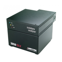
All analyzer functions are controlled by a microprocessor housed within the
smart Sensor. Communication with the smart Sensor is achieved through the
following connections:
• One analog input, 4–20 mA.
• One analog output, 4–20 mA, isolated. Can be either loop powered or
powered by the analyzer.
• Three alarm contacts (dry relay contacts).
• One RS-232 serial port.
• One RS-485 serial port.
The 3050-DO Analyzer has no local user programming functions. It requires se-
rial communication with an external PC for conguration. Once congured, the
analyzer is capable of standalone operation. The analyzer is factory congured
and packaged with Congurator Software for initial setup of operating param-
eters. For enhanced interface and process monitoring, AMETEK oers optional
System 2000 Software with graphical user interface to record and process your
data in a Windows 95/NT format. User provided software may also be used
with the 3050 serial ports.
Verication
The 3050-DO Analyzer has a built-in Moisture Generator for onboard Verica-
tion. A portion of the dry Reference gas ows through the Moisture Generator
where a known amount of moisture is added. When Cell Verication is initiat-
ed, the QCM Sensor is alternately exposed to gas from the Moisture Generator
and dry Reference gas. The moisture value is compared to a stored value. The
Sensor can make an adjustment if the value is within a tolerance band. If the
value is outside the tolerance band, an alarm will activate.
Since the Moisture Generator uses a dried portion of Sample gas, Sensor
Verication is performed on a sample of the process gas. This yields the most
realistic test of the sensors performance under process conditions.
Overview | 1-3

 Loading...


