EasyManua.ls Logo

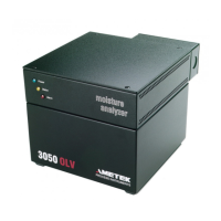
Ametek 3050-AM User Manual

Ametek 3050-AM
96 pages
To Next Page IconTo Next Page
Page #1 background imageLoading...
Page #1 background image
3050 AM Moisture Analyzer
User Manual
Process Instruments
455 Corporate Boulevard
Newark, DE 19702
PN 305804901, Rev YA
Configurator Version 3.0

Table of Contents

Question and Answer IconNeed help?

Do you have a question about the Ametek 3050-AM and is the answer not in the manual?

Ametek 3050-AM Specifications

General IconGeneral
BrandAmetek
Model3050-AM
CategoryMeasuring Instruments
LanguageEnglish

Summary

Safety Notes

Electrical Safety

Information on safe electrical connections and precautions for the analyzer.

Grounding

Mandatory grounding requirements for instrument safety and performance.

Sample Gas Safety

Potential hazards and precautions related to sample gas handling.

Electromagnetic Compatibility (EMC)

Special Warnings and Information

Hazardous Location Equipment Use

Information on using equipment in Class I, Division 2 hazardous locations.

Warranty and Claims

Controller and Communications

Moisture Sensor

Zero Gas Module and Analyzer Zeroing

Analyzer Specifications

Measurement Performance

Details on the analyzer's calibrated range, limit of detection, accuracy, and response time.

Operational Specifications

Installation and Start-Up

Analyzer Requirements

Space, utility, electrical, and environmental requirements for analyzer installation.

Installation Connections

Details on user-supplied items, rear panel, dryer, gas, electrical, and communication connections.

Analyzer Installation Requirements

Utility and Sample Requirements

Analyzer Installation Details

Rear Panel Connections

Installing the Dryers

Gas Connections

Electrical Connections

Power Connection

Communication Connections

Initial Start-Up and Dry-Down

Start-Up Procedures

Accelerated Dry-Down Procedure

Steps to reduce the time required for the analyzer to dry down.

Performing an Initial Zero Cycle

Instructions for initiating and completing the analyzer's first zero cycle.

Zero Key Functions

Alarm Key Functions

Range Key Functions

Configuration Settings (Config Key)

Communication Settings

System Test Procedures

Serial Communications Protocol

Serial Communication Commands

Serial Command Details

Serial Command Operations

Troubleshooting Alarms

Service and Parts

Parts Replacement Overview

General caution for disconnecting power before replacing parts.

Sensor Maintenance

Capillary Replacement

Proportional Solenoid Valves

Installing New Solenoid Valve

Dryer Maintenance

Installing New Dryer

Electronic Module Maintenance

Printed Circuit Board (PCB) Replacement

Pilot Valve Manifold Service

Replacement Parts List

PC Interface and Software

Configurator Software Installation

Step-by-step instructions for installing the configurator software from CD-ROM.

Software Configuration

General Tab Configuration

Viewing current configuration and defining analyzer/PC communication parameters.

PC Communications Setup

Configuring COM port, Baud Rate, and Port Type for PC communication.

Software Status and Monitoring

Software Setup Tab

Software Schedule Tab

Related product manuals