PN 305725901, Rev YF
RS-485 Cables, Multiple 3050-DO Analyzers
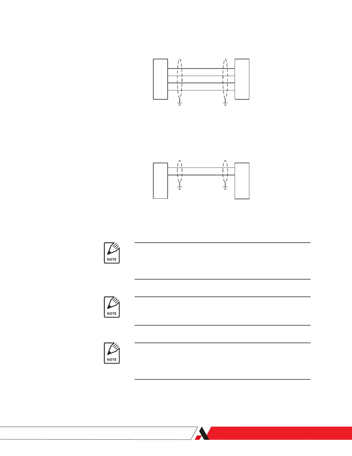
Figure 2-8.
RS-485 Cables,
Multiple 3050-DO Analyzers.
24
25
28
29
24
25
28
29
RX+(B)
RX- (A)
TX+(B)
TX- (A)
RS485 OUT
3050
RS485 Cables, Multiple 3050-DO Analyzers
4 wire
2 wire
24
25
24
25
RX/TX+(B)
RX/TX- (A)
RS485 OUT
3050
RS485 IN
3050
RS485 IN
3050
Notes
1. Total cab le length not to e xceed 1000m. Cab le should be lo w capacitance type f or use in
RS-485 applications (nominal impedance of 120 Ohms , shielded twisted pairs).F or example ,
Belden 9841 in two wire applications , Belden 9842 in 4 wire applications .
2. Install ter minator plug (p/n 305 900 901) in RS485 OUT position of last controller in
networks with both single and multiple 3050 analyzers.
3. Cab le shields should be tied to TB3-GND at each 3050. If this is not possib le (f or
example , in the case of a ground loop) , tie the shield at the PC or DCS to chassis and all
other shields to ear th through a 0.1uF @ 500 V capacitor .
TB3
TB3
TB3
TB3
Total cable length not to exceed 1000 m. Cable should be low capaci-
tance type for use in RS-485 applications (nominal impedance of 120
ohms, shielded twisted pairs). For example, Belden 9841 in 2-wire ap-
plications, Belden 9842 in 4-wire applications.
Install the terminator plug (PN 305900901) in the RS-485 OUT position
of the last controller in networks with both single and multiple 3050
Analyzers.
Cable shields should be tied to TB3-GND at each 3050 Analyzer. If this
is not possible (for example, in the case of a ground loop), tie the shield
at the PC or DCS to the chassis and all other shields to earth through a
0.1uF @ 500 V capacitor.
Installation and Start-Up | 2-15
 Loading...


