PN 305725901, Rev YF
Example:
The value of SystemState is 12612 which is the same as 3144 hexadecimal
number. Corresponding alarms started from the list signicant bit are: Invalid
Reading, Calibration Failure, Flow Alarm, Moisture Generator Date, and
Dryer Alarm.
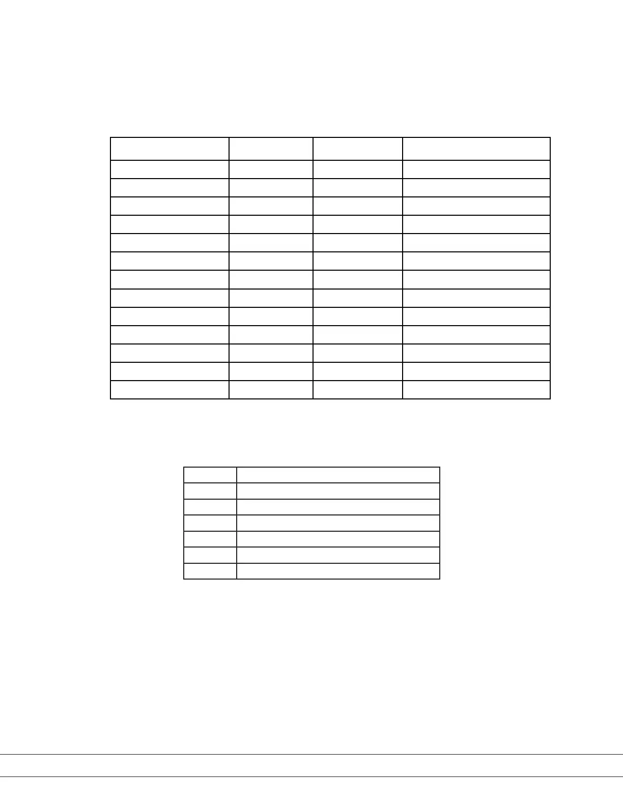
Alarm Name System State Bit Number of blinks Comment
Memory Failure Bit 4
1
System Alarm
Sensor Failure Bit 5
2
Frequency & Sensor Access
Calibration Failure Bit 6
3
Span Out of Limit
Oven Temperature Out Bit 7
4
Temperature Out of Limit
Flow Out of Range Bit 8
5
System Alarm
Battery Low Bit 9
6
Battery State
Reference Gas Alarm Bit 10 Warnings
7
Set if Delta Frequency < -0.3 Hz
Enclosure Temperature Bit 11
8
Temp >70 degrees C
Moisture Generator Date Bit 12 N /A Good for Two (2) Years
Dryer Alarm Bit 13 10 Exceeding PPM Hours
Concentration Alarm Bit 0 – Bit1 11 Concentration Out of Range
Invalid Reading Bit 2 11 Verication or System Alarm
Process Pressure Bit 3 11 Process Pressure Out of Limits
Register #25 is a ModbusCommand register. This register allows sending spe-
cial commands to the 3050 Analyzer as shown in the table below.
Value Command Description
71 Start Verication Cycle
76 Load Sensor Memory
81 Quit Verication Cycle
82 Reset Analyzer
84 Start/Stop Test Mode
90 Start Zero Cycle
The last set of registers starting from #141 represents ASCII strings. Each reg-
ister is holding two ASCII characters. End of the string should be marked with
integer number of zero (‘0’). For example, if the AnalyzerName variable is set to
“Dev”, the holding register values are (considering that high byte located rst)
#141 ( 68, 101) and #142 ( 118, 0 ). Note that zero (‘0’) indicates the end of the
ASCII string.
6-10 | 3050-DO Moisture Analyzer
 Loading...


