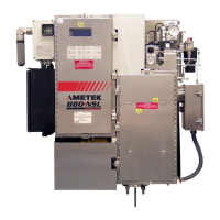
Do you have a question about the Ametek Thermox Series 2000 WDG-IV and is the answer not in the manual?
| Enclosure Rating | NEMA 4X/IP66 |
|---|---|
| Measurement Type | Oxygen |
| Technology | Zirconium Oxide |
| Measurement Range | 0-25% O2 |
| Response Time | <5 seconds |
| Output | 4-20 mA |
| Power | 50/60 Hz |
Emphasizes safe electrical practices for analyzer operation and maintenance.
Mandates instrument grounding for performance and safety compliance.
Covers wiring, overload, grounding, covers, fuses, and atmosphere operation.
Includes using proper power source and not operating with suspected failures.
Explains how the sensor functions in flue gas analysis applications.
Explains the function and operation of the combustibles detector.
Explains the function and operation of the methane detector.
Details specifications for the Series 2000 control unit.
Lists specifications for the WDG-IV sensor.
Lists specifications for the WDG-IVC sensor.
Lists specifications for the WDG-IVCM sensor.
Lists specifications for the WDG-IVC sensor with 0-500 PPM range.
Details specifications for the Remote Calibration Unit (RCU).
Guidelines for selecting an appropriate installation location for the analyzer.
Instructions for checking shipping contents for damage.
Details procedures for mounting and connecting sensor components.
Instructions for installing the probe heater.
Instructions for installing the exhaust tube.
Guidelines and considerations for mounting the sensor to the process.
Details the preferred method for sensor flush mounting.
Alternative method for mounting the sensor using a pipe nipple.
Details required calibration gases, tubing, and Z-purge connections.
Instructions for mounting the Series 2000 control unit in various configurations.
General requirements and procedures for controller and sensor wiring.
Required wiring connections between the control unit and the sensor.
Details standard and optional current output connections on the control unit.
Describes standard and option-specific alarm contact connections.
Details RS-485 communication connections (2-wire and 4-wire).
Instructions for installing or removing option cards in the control unit.
Describes control unit areas, keys, and system password settings.
Explains menu options for configuring the control unit, including display and sensor settings.
Steps to define and enter the system process pressure value.
Procedures for running internal diagnostics and checking system serial numbers.
Steps to select and configure the correct sensor type.
Configuration parameters for RS-485 serial communications.
Menu for configuring analog output signals, ports, and ranges.
Menu for configuring alarm functions, set points, relays, and logs.
Defines calibration, verification, span, and zero gas terms.
Describes automatic, remote, and manual calibration types.
Steps to perform automatic, remote, or manual calibration/verification.
Steps to initiate remote calibration or verification processes.
Steps for performing manual calibration or verification.
Entering calibration gas values for oxygen and combustibles.
Procedures for injecting calibration gases manually or automatically.
Setting automatic calibration cycle timers and durations.
Enables or disables automatic calibration/verification cycles.
Defines duration for span and zero calibration gas flow.
Defines recovery time after calibration for system stabilization.
Lists and explains system messages displayed on the control unit.
Lists and explains error messages indicating analyzer operation problems.
Procedures to check sensor areas for possible problems.
Procedures to check sensor wiring for problems.
Checks related to calibration gas, aspirator, and RCU setup.
Checks for adequate AC voltage supply to the sensor and furnace.
Procedures for checking furnace operation and resistance.
General steps for diagnosing and resolving inaccurate readings.
Procedures for checking the system for leaks to ensure accurate readings.
Steps to check for and clear plugged plumbing in the sensor.
Explains the status indicated by LEDs on the control unit and option cards.
Step-by-step instructions for replacing the oxygen cell.
Instructions for replacing the thermocouple in the sensor.
Steps for replacing the furnace component of the sensor.
Instructions for replacing the hot-wire combustibles detector.
Instructions for replacing the RTD combustibles detector.
Wiring diagram for connecting box heaters to the sensor board.
List of part numbers for sensor, RCU, and control unit components.
Defines the RS-485 communication protocols and word format.
Details the structure of command messages for serial communication.
Lists common commands for reading and writing analyzer data.
Commands used during initial serial communication design and testing.
Describes successful and failure communication responses from the analyzer.
Summarizes variable locations, names, and descriptions for serial communication.
Lists the menu options available under the Setup Key.
Lists the menu options available under the Analog Range Key.
Lists the menu options available under the Alarm Key.
Lists the menu options available under the Calibrate Key.
How to power current outputs using an external voltage source.
Example connection for modulating an external power loop with current outputs.


