X
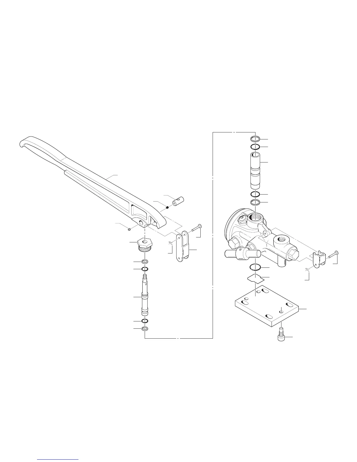
Figure 1.2 • Hydraulic Hand Pump Type T Assembly
Detail B
12
*
13
18
16
15
14
17
26
27
**
25
25
26
29
30
31
28
19
21
22
20
24
23
18
(17)
16
The pump handle and piston can be removed as an
assembly for inspection of the o-rings and backup rings.
Remove the upper clevis pin (15) and cotter hair pin (17).
Then unscrew the cylinder retaining plug (18) and pull
the assembly straight up.
At the bottom of the pressure stroke, the piston should
rest on the body plate liner (29) before the pump handle
hits the cylinder retaining plug. If it does not, loosen the
piston pin screw (14), insert a small rod in the hole
provided at the top of the piston, and rotate the piston
counterclock-wise to raise the pump handle. When the
pump handle is raised to the proper height, tighten the
piston pin screw.
*
The pump cylinder must be removed and reassembled
from the top. Otherwise, the o-rings may be cut by the
angular, intersecting hold in the lower portion of the
pump body casting bore. To remove the cylinder, rst
detach the body plate (30) and body plate liner (29), then
push the cylinder up and out from the bottom.
On reassembly, moisten the o-rings with system uid and
rotate the cylinder as you insert it, to avoid cutting or
pinching the o-rings. A tapered piece of wood may be
helpful to rotate the cylinder.
**