M. Install electrical system
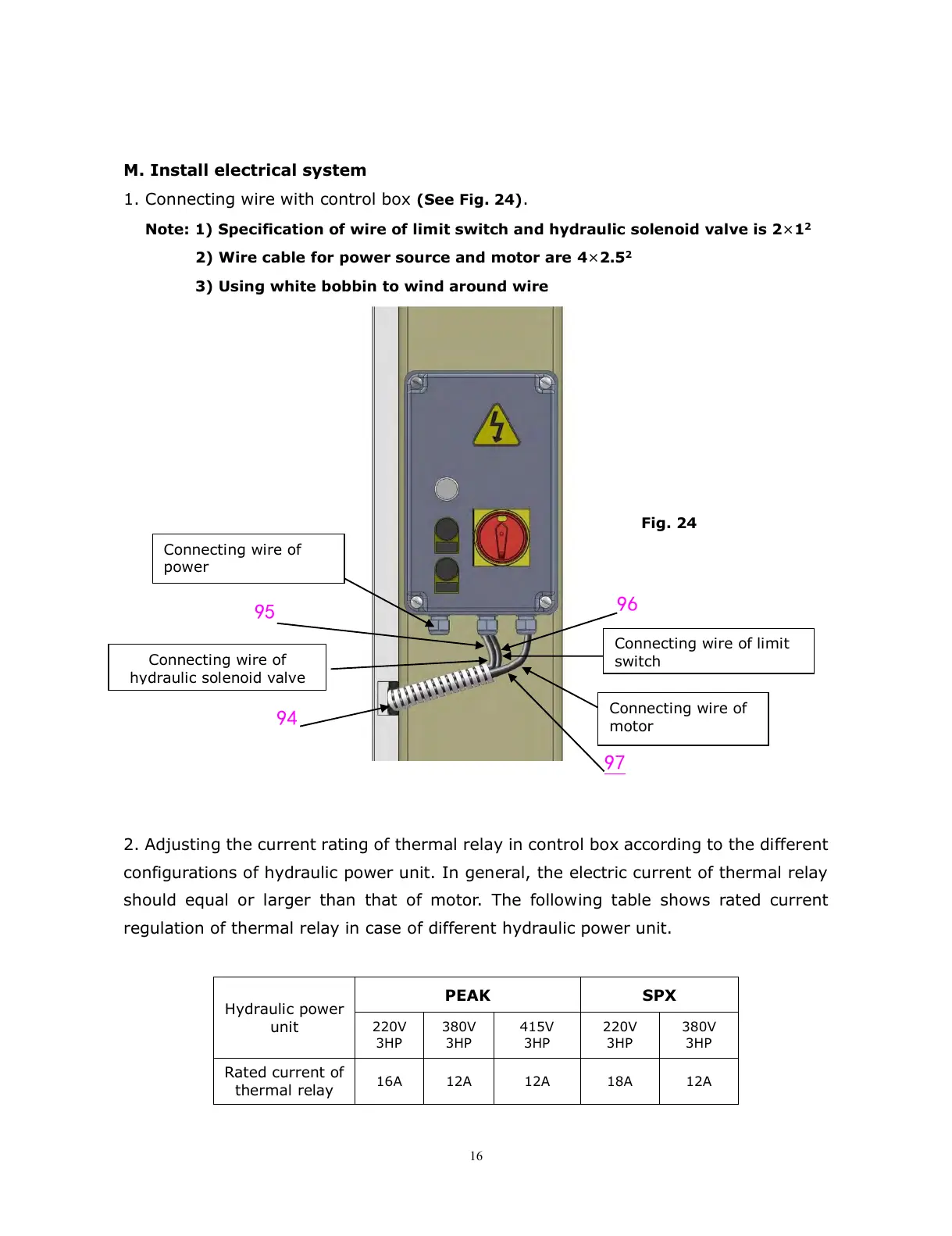
1. Connecting wire with control box (See Fig. 24).
Note: 1) Specification of wire of limit switch and hydraulic solenoid valve is 2×1
2
2) Wire cable for power source and motor are 4×2.5
2
3) Using white bobbin to wind around wire
2. Adjusting the current rating of thermal relay in control box according to the different
configurations of hydraulic power unit. In general, the electric current of thermal relay
should equal or larger than that of motor. The following table shows rated current
regulation of thermal relay in case of different hydraulic power unit.