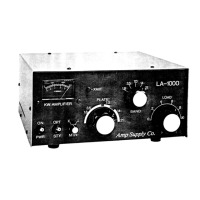
6. Preset the LA-1000 meter switch to the I (current)
position. Key your exciter and begin to increase the CW
carrier level untill reaching approximately 300 mA on the
plate current. Quickly turn the TUNE and LOAD control for
maximum output on your wattmeter. Contimue to Increase
your exciters output untill you reach approximately 600mA
(.6A X 1166v = 700 watt DC input).
7. Repeak your Tune and Load controls for maximum output.
To operate SSB, tune the LA-1000 as stated above. When
fully tuned in CW, simply change your exciter to SSB. No
further adjustments to the LA-1000 are required.
THEORY OF OPERATION
Power Supply
After the LA-1000 has been installed according to
the instructions, and power is applied, SI is used for in
itia l turn on. AC is applied to Tl, the main power trans
former, and to the fan, Bl. The three secondary windings
of the transformer are used to produce filiment voltage
(6.3v) relay control voltage (12v) and HV. The I2v DC is
developed by use of a half wave rectifier. When power is
applied, meter lamp X2 and LED D1 (internal part of SI)
will light.
The closing of S2 allows 12 v to be applied to the
relays (RL2-6) in the tuned input, the QSK module, the Xmi
lamp XI and the LED D2 ( internal part of the S2)
The high voltage section is made up of 8 diodes in
a bridge circut. Each diode (D4-11) is a 3 amp lOOOpiv in
parallel with a .01 uf capacitor (C23-30 for transient pro
tection, and a 470 Kohm h w resistor (R 3-10} for equal
ization. For filterin g , 3 125 uf 0500 v capacitors ( 031-
are used in series. Each has a 10GK ohm 2w bleeder resis
tor (R15-17) in parallel.
RF Operation.
When S2 is in the OPT mode, 12 v is applied to the
tuned input relays, the QSK module and the transmitter ligf
The band switch w ill select a ground path for one of the
tuned input relays, allowing the proper section to be plac<
 Loading...