in series with the RF path. When the exciter is
keyed» it provides a closed circuit for the trans
mitter lamp and the QSK module. The QSK module
in turn keys the antenna relay RL-1.
RF from the exciter flows into Jl, through
the proper input circuit, through C12, 13 to
the cathodes of tubes V1-V4. Diode D12 pro
vides bias for the tubes.
PC 1-4 are parasitic chokes. The RF comes
from the tubes, through C35 to the tank circuit
L6, 17, C36, C37. The tank is tuned for max
imum transfer of RF to the antenna through J3
RFC 3 is to protect the antenna from DC poten
tial .
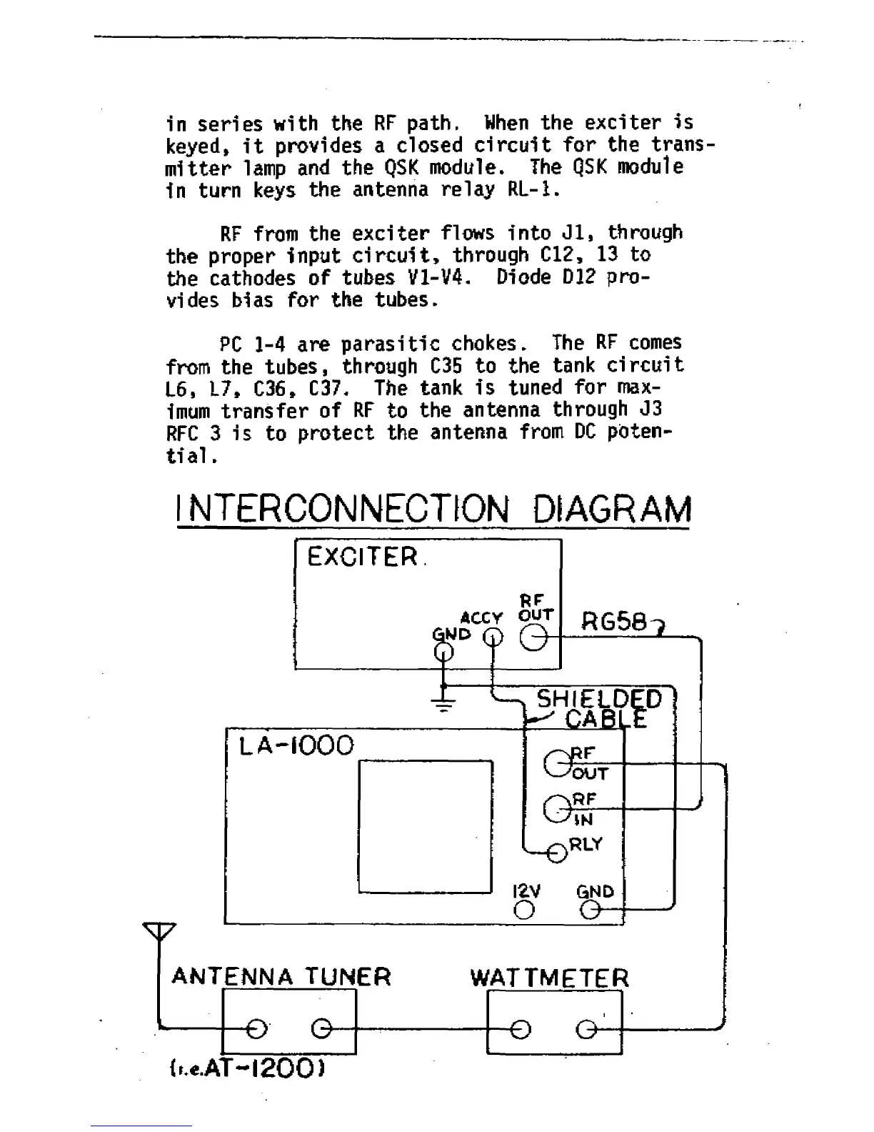
I INTERCONNECTION DIAGRAM
EXCITER
RF
ACC Y OUT
wd c?)
RG58-?
<-.«.AT-l2 0 0 >