www.SteamPoweredRadio.Com
5-4
10
....
+
•
I
,
'
110
....
+
0
....
+
I
j
I
I
I
I
'
0
....
+
10
+
Ill
0.
-
~
....
I
t-
\
0
I
I
;~
J
I
,
I
I
,
10
+
I
I
r
I
0
ll)
Cll
.s-
~
C"l
I
C"l
1,
I
II
• j
I I
,~
I
,
I
,
ll)
r\
,
0
....
I
I
j
0
....
I
I
ll)
....
I
I
I
I
•
I
'
'
.
I
10
....
I
0
0
NO
0
N
00
N
~
0
0
rz:I
fll
op:;
....
0
rz:I
~p,.
00
a:>
~
co
0
>4
0
'I$'
t-5
t;
:z;
rz:I
5'
N
~
rs..
0
....
0
....
00
U)
,ti
~
>
E-t
>
:z;
0
~
~<
oi5
0~
~~
~
p:;
0
el
g
rs..
....
0
~
~
p,.
P-t
~
~
~
<::
~
0
....
~
Oo
<o
p,.
0
•"'
E-t
$,,
E-t
0
;g
[i]
'I$'
"'
...,
~
C
~
...,
"'
~
E-t
...
....
-~
B
:-';::-
--
"'-
ei
~
0
~
E-t
"'
...,
fll
~
~
""
C
...
"'-
"'
~
11
......
V"\
-~
R.,
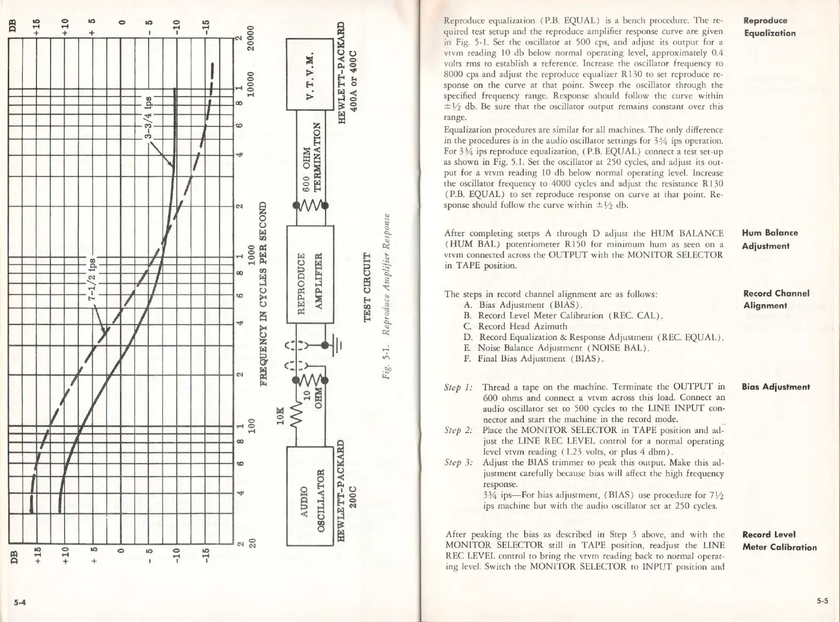
Reproduce equalization ( P.B.
EQUAL)
is a bench procedure.
The
re-
quired
test
setup
and
the
reproduce amplifier response curve
are
given
in Fig. 5-1. Ser
the
oscillaror ar
500
cp
s,
and ad just its
output
for a
vcvm reading 10
db
below norm
al
operating
level,
approx
imately 0.4
volts
rms
co
establish a reference. Increase
the
oscillator frequency
to
8000
cps and adjust
the
reproduce equalizer R 130
to
set reproduce re-
sponse on the curve
at
that
point. Sweep rhe oscillator through the
spec
ifi
ed
frequency range. Response should follow
the
curve
within
± ½ db. Be
sure
that
the
oscillator
output
remains constant over this
range.
Equalization procedures
are
similar for all machines.
The
only difference
in
the
procedures
is
in
the
audio oscillacor settings for
3¾
ips operation.
For
3¾
ips reproduce equalization, ( P.B.
EQUAL)
conne
ct
a test set-up
as shown
in
Fig
.
5.
l.
Set
the
oscillaror
at
250
cycles, and adjust its out-
put
for a vtvm reading
IO
db
below normal
operating
level. Increase
the
oscillator frequen
cy
to
4000
cycles
and
ad
just
the
resistance R 130
( P.B.
EQUAL)
to
set-
repro
duce
response
on
curve
at
that
po
int. Re-
sponse should follow
th
e curve
within
± ½ db.
After
completing srerps A through D
ad
ju
st
the
HUM
BALANCE
( H
UM
BAL)
potentiometer
Rl
50
for
minimum
hum as seen
on
a
vtvm connected across the
OUTPUT
wi
th
the
MONITOR
SELECTOR
in
TAPE
pos
it
ion.
The
steps in record channel alignment are as follows:
A. Bias
Adjustment
(BIAS
).
B. Record Level
Meter
Ca
libration ( REC.
CAL).
C. Record
Head
Azimuth
D. Record Equalization & Response
Adju
stme
nt
(REC.
EQUAL
) .
E.
Noise
Balance Ad jusrment (
NOISE
BAL
).
F. Final Bias
Adjustment
(BIAS
).
Step
1:
Thread
a cape
on
the
machine.
Terminate
the
OUTPUT
in
600
ohms
and
connect a
vtvm
across
ch
is load. Co
nnect
an
audio oscillaror
set
to
500
cycles ro
the
LINE
INPUT
con-
nector
and
start
the
machine
in
the
record mode.
Step 2: Place
the
MONITOR
SELECTOR in
TAPE
positi
on
and ad--
just
the
LINE
REC
LEVEL control for a normal
operating
level
vtvm
reading ( 1.23 voles,
or
plus 4
dbm).
Step 3:
Adjust
the
BIAS
trimmer
ro peak this output. Make this ad-
justment
carefully because bias will a
ff
ect
the
high frequency
response.
3¾
ips-
For
bias ad ju
stment
, (BIAS) use procedure for
7½
ips machine
but
with
the
audio oscillaror set
at
250
cycles.
After
peaking rhe bias as described in
Step
3 above, and
with
the
MONITOR
SELECTOR still in
TAPE
position, readjust
the
UNE
REC
LEVEL control
co
bring
the
vtvm
reading back
to
normal operat-
ing level. Switch
the
MONITOR
SELECTOR
to I
NPUT
position and
Reproduce
Equalization
Hum
Balance
Adjustment
Record Channel
Alignment
Bias Adjustment
Record
level
Meter
Calibration
5-5