www.SteamPoweredRadio.Com
Record
level
Meter
Calibration
Record
Head
Azimuth
Adjustment
Record Equalization
Adjustment
(Alternat
e Procedure)
5-6
adjust
the
RE
C. CAL potentiometer R 114
unc
il normal operating level
is read on
the
vtvm.
The
v-u mer
er
is
now calibrated, and should read
zero
v-
u ± ½ db with the
MON
I
TOR
SELECTOR switch
pl
aced on
the INPUT
or
TAPE
position.
Step I: Thread a rape on
the
machine. Terminate rhe
OUTPUT
in
600
ohms and connect a vcvm across
ch
is load. Connect an
audio oscillator
sec
ar 250 cps
co
the LINE IN P
UT
Place che
MON
ITOR SELECTOR switch on
TAPE
position.
Scare
rhe
machine in the record mode, and adjust
che
LINE REC LEVEL
concrol for a vtvm reading 20
db
below normal
operat
i
ng
level.
NO
TE
W ith the REC LEVEL controls
at
minimum, the bias
pi
ckup
as measured on the vcvm should be
30
db
below
normal operating level.
If difficulty is experienced be-
cause of bias, connect a wave crap in parallel with
the
600
ohm terminating resisrance. This trap can be a series
LC circuit resonant
at
approximately 100 kc.
Step 2: Increase rhe oscillacor setting
co
I
J,000
cycles. Insert a small
screwdriver through rhe access hole nearest the center
of
the
head shield and adjust the record head azimuth screw for
maxi
mum
output. Be sure
co
sec
at
rhe correcc peak as de-
scribed under reproduce head azimuth adjustment seep 2.
(REC. EQUAL
).
StefJ
I:
Record equalization can be accomplished without disconnect-
ing the electronic assembly from rhe rape rransporr.
The
re-
produce ch,mnei 1mtst be properly
,1/ig11ed
and
the
record head
in good
concli
t
io,z.
lf
these requirements are sarisfied, thread
a cape on rhe machine.
Terminate
rhe
OUTPUT
in
600
ohms
and
connea
the vcvm across chis load. Ser an audio oscillaror
tU
250 cycles and connect it ro the LINE
INPUT
connecror.
Place
the
MON
I
TOR
SELECTOR switch in
TAPE
position,
and srart the machine in
tht
record mode.
Adjust the LINE REC LEVEL control for a vtvm reading
20
db
below normal operating level. Increase the oscillacor setting
co
8000
cps and adjust
the
REC. EQUAL capacitor
Cl07
for
a vrvm reading 20
db
below normal operating level. Fre-
quency response can now be checked by sweeping
the
osci
l-
lator through the range given in the specifications.
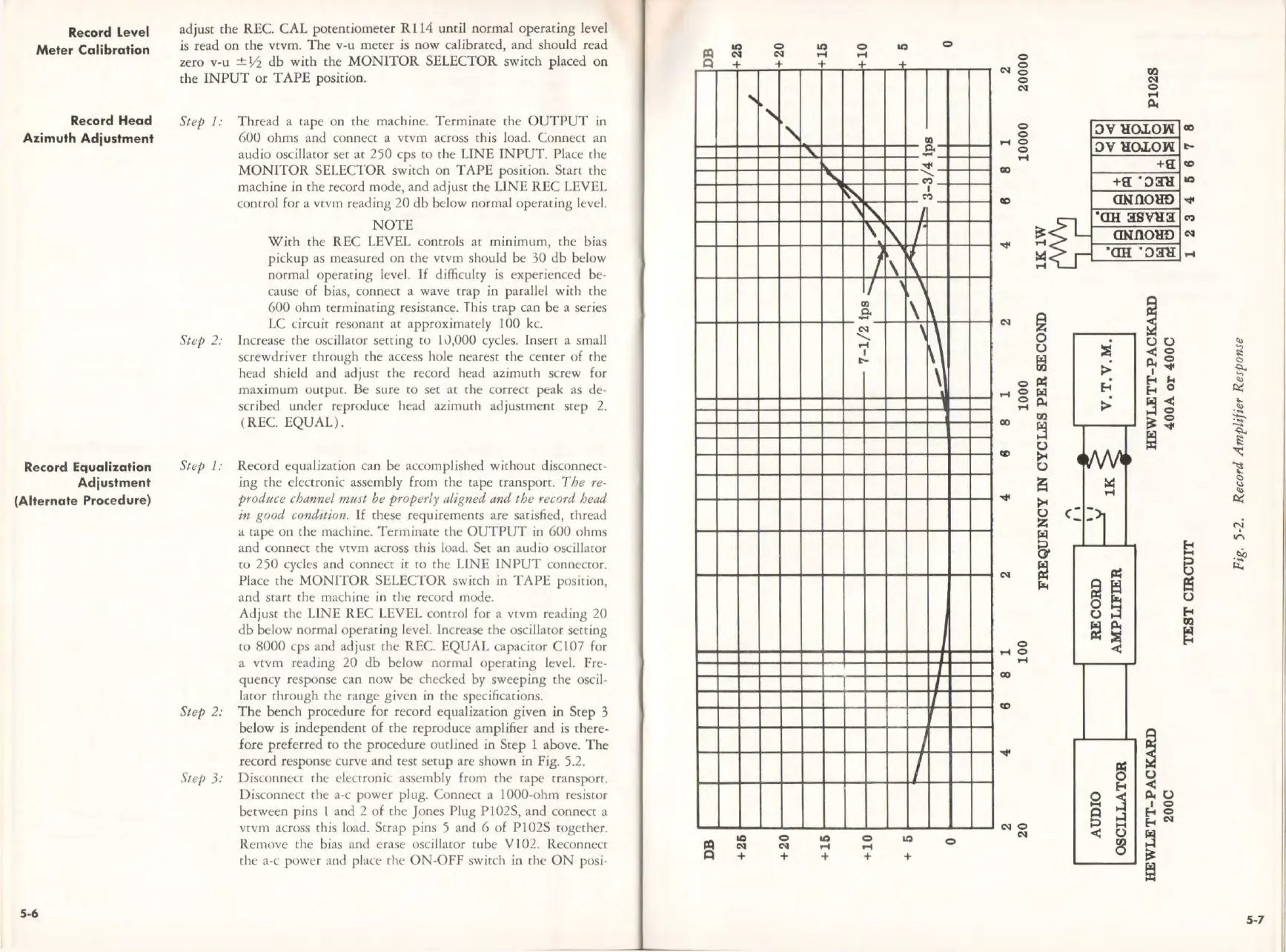
Step 2: The bench procedure for record equalization given in Step 3
bel
ow
is independent
of
the
reproduce amplifier and
is
there-
fore preferr
ed
to rhe procedure outlined
in
Step l above. The
record response curve and rest setup are shown in Fig. 5.2.
Ste/J
3: Distonnect rhe
denronic
assembly from the cape transport.
Disconnect
che
a-c power plug. Connect a 1000-ohm resistor
between pins I and 2 of
the
Jones Plug PI 02S, and connect a
vrvm across this load. Scrap pins 5 and 6
of
Pl02S
cogether.
Remove the bias and erase oscillawr rube
Vi
02. Reconnecc
the
a-c
powtr
:mJ place rhe ON-OFF switch in
the
ON
posi-
+
LC
N
+
...
+
"',
'
0
N
+
'-
+
'
LC
.-1
+
0
.-1
"
'I'..
I\
I
I/
a>
E<
CN
'
.-1
I
t--
0
.-1
+
LC
0
a>
0.
-
~
M
I
M
j
\.
I
'
\
\
' '
~
\ \
\'
\
\
I
'
I
IQ
+
I
I
I
0
0
CN
g
fl.I
0
N
CN
0
.-1
ll4
0
';)V
HOJ.O:W
0
CID
.-1
0
0
';)V
HOJ.O:W
t--
.-1
+a:
GO
co
+a:
. ';):ill
IQ
410
CINaOlID
~
0
0H
:JSVll:i
M
~
CINfiOlID
CN
-.ft
.-1
~
.OH .
';):Ill
.-1
.-1
CN
~
~
0
C) C)
<u
C)
)l
._,
<o
~
~
ll40
<:>
>
I
-.ft
t
0
~
f-4
...
.-1
0
ra1
f-4
f-4
0
~
0
ll4
>
fj
~
...
.-1
<u
I'll
...
GO
~~
:t;-
~
~
C)
[i]
~
co
~
~
C)
~
~
~
<:>
"
.-1
<u
-.ft
~
~
C)
c::
z
~
i:,,::i
""
5'
E-
➔
-~
....
~
~
8
~
CN
~
~
~
ei
~
C)
C)
~
E-
➔
~
Ill
!XI
)l
~
0
<
.-1
0
.-1
GO
(0
~
-.ft
~
C)
f-4
<
e
:s
Ill U
10
§
~
f-4
0
NO
....
f-4
N
N
<
C)
~
~
~
fi1
5-7
 Loading...