www.SteamPoweredRadio.Com
Magn
eti
c
Head
Ma
gneti
za
ti
on
Curv
e
Bias
2-2
The
magnetic field
is
produced in
rh
e
gap
of a recording head,
over which the recording
tap
e passes.
Th
e recording head is a ring-
shaped electromagnet ( See
Fi
g.
2-2).
Ir
consists of an incomplete ring
of highly permeable material inserted in a coil of wire.
The
discontin-
uity in
the
ring
forms
the
ga
p,
a
nd
the ring
is
rhe core of the electro-
magnet.
-
------
e
------~
""'
Fig. 2-2. Recording Head
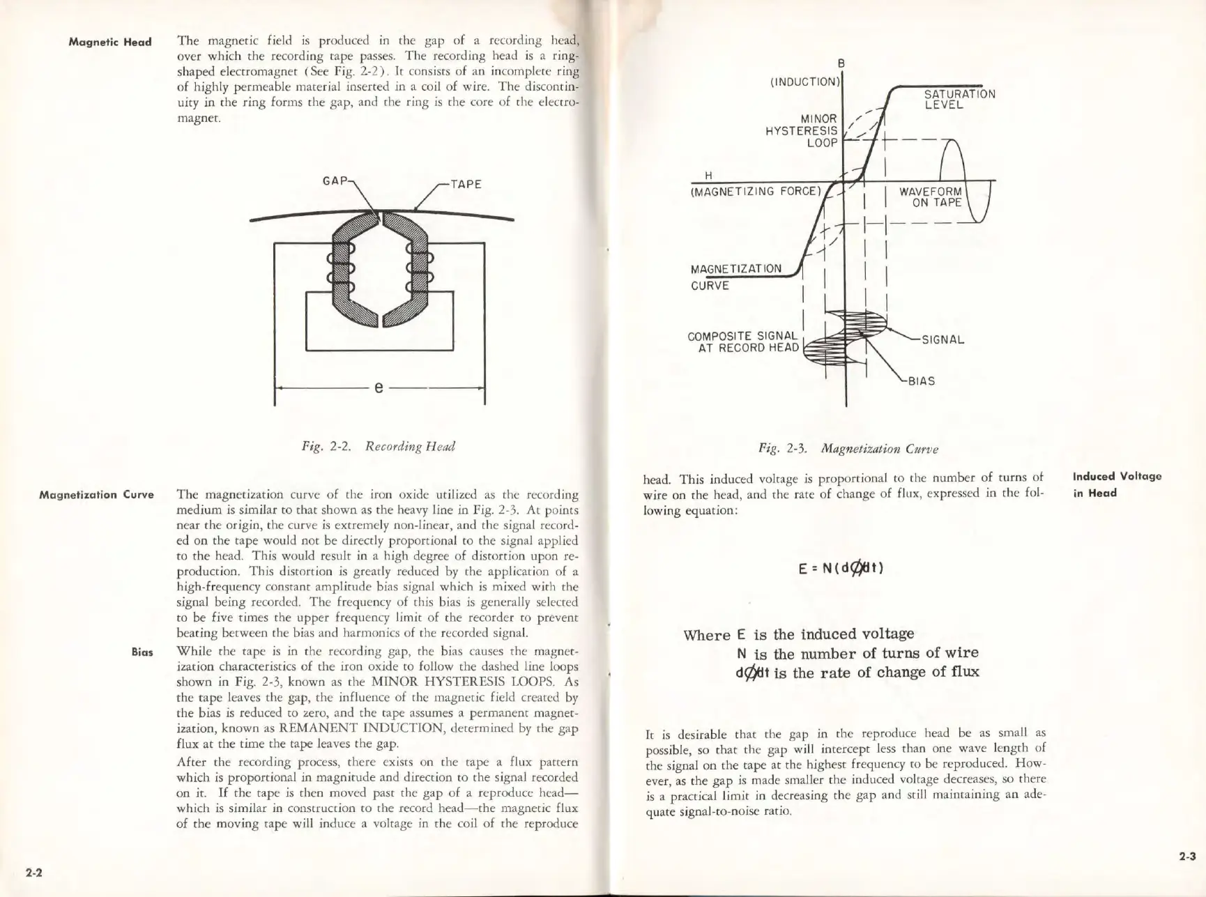
The
magnetization curve of the i
ro
n ox
id
e utilized as the recording
medium is simil
ar
to that shown
as
the heavy line
in
Fig. 2-3. At points
near
the
origin, the c
ur
ve
is
extremely non-linear, and the signal record-
ed on the cape would n
oc
be directly proportional to the signal
app
li
ed
to
the
head.
Thi
s would result in a high degree of distortion upon re-
production.
This
distortion is greatly reduced by the application of a
hi
gh-frequency constant am
plitude
bias signal which is mixed with
the
signal being recorded.
Th
e frequen
cy
of this bias is genera
lly
selected
to be five ti.mes the
upp
er fre
qu
ency l
im
it
of
the recorder to
pr
.event
beating between the
bi
as and harmonics of rhe recorded signa
l.
While
the
tape is in
the
recording gap, the bias causes the magnet-
ization characte
ri
stics
of
the iron oxide to follow the dashed line loops
shown
in
Fi
g. 2-3, known as the
MlNOR
HYST
E
RE
SIS LOOPS. As
th
e t
ape
leaves the gap,
the
influence of the magnetic field created by
th
e
bi
as
is
reduced to zero, and
the
tape assumes a p
erma
nent magnet-
ization, known as
REMANEN
T
INDUCTION,
determined
by
the gap
flux
at
th
e time the tape leaves
the
ga
p.
After
the
recording process, there exists on
ch
e cape a flux paccero
which is proportional in magnicude and
di
rection to the signal recorded
on it.
If
the
rape is then
mov
ed
past
the
gap
of
a reproduce
head-
which is similar in construction ro the record
hea<l-rhe
magnetic flux
of
th
e moving rape will induce a voltage in the coil
of
the
re
pr
oduce
B
(INDUCTION)
H
(
MAGNETIZ
I
NG
FORCE)
MAGNETIZATION
CURVE
CO
MPOSITE SIGNAL
AT RECORD
HE
AD
I
I
SATURATION
LEVEL
I I
1-1---
1 I
I I
I I
SIGNAL
Pig. 2-3. Magnetization Cttrve
head. This i
nduc
ed voltage is proportion
al
to
the
numb
er
of
cums
ot
wire on the head, and the rare of change
of
flux,
exp
ressed in the fol-
lowing equation:
E=N(d¢)tft)
Wher e E is
the
induc
ed
vo
lt
age
N
is
th
e
numb
er of
turns
of
wir
e
d~t
is
th
e
ra
te
of
chan
ge of
flux
It
is
desirable that
the
gap in the reproduce head be as small as
possible, so
that
the
gap will interce
pt
less than one wave
le
n
gth
of
the signal
on
the
tape
at
the highest freq
ue
ncy
to
be reproduced. How-
ever,
as
the
gap
is made smaller
the
induced voltage decreases, so there
is a practical limit in decreasing the gap and st
ill
maintaining an ade-
qu
at
e si
gna
l-to-noise ratio.
Induced
Voltag
e
in H
ead
2-3