www.SteamPoweredRadio.Com
2-4
Induced
Voltogc
in
Head
The
voltage induced across the head 1s computed by
the
following
equation:
E =
Bm
V
sin
,,.%
Where
E
is
the
induced
voltage
B
is
the
maximum
flux
density
of
the
recording
material
V
is
the
velocity
of
the
tape
over
the
head
w
is
the
gap
width
~
is
the
wavelength
of
the
signal
on
the
tape.
From this expression
it
can be seen chat
the
voltage across the coil
increases directly as the velocity increases a
nd
as the wave-length de-
creases ( frequen
cy
increa
ses).
If
th
e rape velocity and
ga
p width a
re
assumed
to
be consranc, the
output
voltage from
the
head
is
directly
pro
-
portional
to
the frequency, as long as the wave length on the rape is
l
arge
compared co
the
gap
width.
This
results ;n
an
output vs.
fr
e
quen
cy
charact
er
istic such as shown in c
ur
ve A of Fig. 2-4.
The
voltage does
not
continue
co
rise indefinite
ly
.
As
electrical losses in the core mate-
rial increase,
and
as the wave-length on the rape
ap
proa
ches the same
dimensions as
th
e
repr
oduce head gap, the actual
output
res
em
bl
es curve
B
of
Fig
. 2-4.
OUTPUT
r
(db)
, , r r r r :
I I I I I I I
+
25
_______
Jr--1--------Jr--j----
----
1--- ♦
-----1
I I I I A I : :
+20
________ J
___
!--------1---~
--------
'
---t----
J
I I I I I I :
l : : I I I I
♦
15
-------
r---r--------r
__
J
______
Jr
-
--'-----
◄
I I I : I : I
+10
________ J
___
!--------1---~-
~~
-
t----
-t----J
I I I I I
'ii
I
: I
!~
I I ' :
+5
--------r--.lr-------
-.\
______
__
J
___
_.,.
____
,
: :
,,__~
I : :, B l
o
--------
:---1-----,
oc,
--t
--------
+--
-r
---
-:
-5
--------
~
---~-
~
--~
__
j
_______
jr_J
____
_
~
I I
Co
I l I : :
-10
________ J
___
J
_______
J
___
i--------!---~-----
1
: : : : : : :
-15
--------
i--
--------~
--J---
------~--~
-
--
--~
I I I : I I I
-20
--------
1
__
J
________
J
___
l-
--
-----
1
---
!
-----
!
I : : : : : :
-
25
------
--i---~--------~---'r
--------~--J
____
_
-4
: : : I I : :
I I I I
10
100
1000
IO
KC
FREQUENCY
Fig.
2-4.
Output
vs. Freqttency
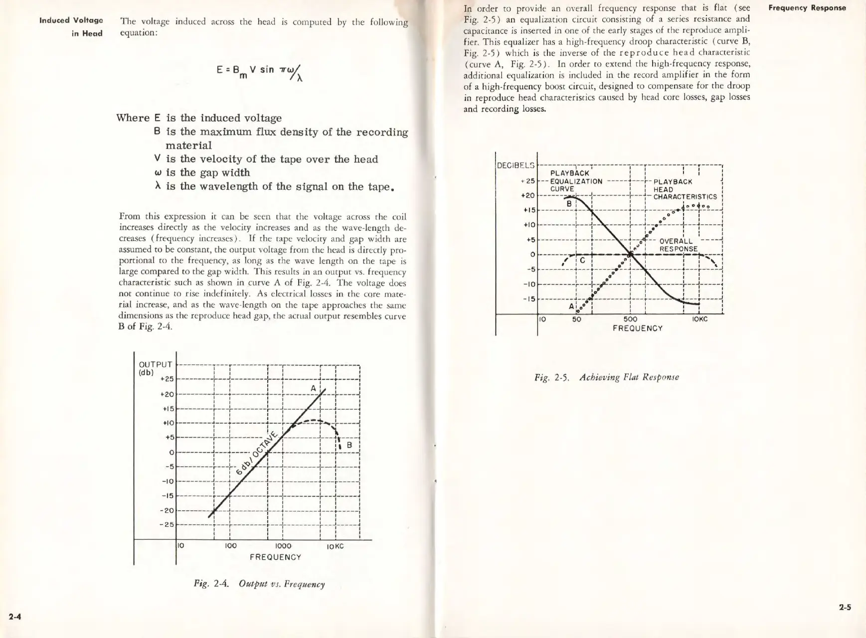
In
order
to
provide an o,·erall frequency response
that
is
flat ( see
Fig.
2-5)
an
equalization circuit consisting
of
a series
re
sistance and
capacitance
is
inse
rt
ed
in one
of
the early srages
of
the re
pr
oduce ampli-
fi
er.
This
equalizer has a high-frequency
droop
characteristic ( curve B,
Fig.
2-5)
which is the inverse
of
the
rep
roduce
head
characc
er
iscic
( curve
A,
Fig.
2-5).
In
or
der
co
extend the high-frequen
cy
response,
additional equal
iz
ation
is
included in the record amplifier in the form
of
a high-frequency boost circuit,
de
signed
to
compensate for the
dr
oop
in reproduce head characteristics caused by head core losses,
gap
losses
and recording losses.
DECIB
ELS
________
_________________
T
____________
T
____
,
PLAYBACK'
! : : : :
•
25
--
EQUA
LI
ZAT
IO
N -----1---~-
PLAYBACK
~
CURVE ' j' HEAO :
+
20
-------
'
--+--
----
-+--,-C
HARACTERISTICS t
B I I I I I • I
♦
15
--------!--
1
--------l---~------
~i
o o
ro
O
__
J
: I : : 0 0 O : : :
♦
1
0
---------~--J
__ -----~--J
__
.!
___
_ J
,--
4
--
---:
: ! : :
••
: ! :
+5
--
------1---
r-----
--1--.f-- OVERALL - -
--
-{
I I I
••
I RESPONSE :
o -----
--
.....,1
I
.._--,-4-
----•
, 1 C 1
0
"
1 : 1 1
',
:
-5
-----
1
--l---!----
......
•
_J __
1
--------!---~---'
J
: :
••
: I : l :
-10
--------~--J,-_,l-----~--~--
----
-t--1-----~
I
1J'
I I I I I
-15
________ J
__
,J
________
J
___
i-
----
1-
--~----J
I O I I I I
A, o
0
I : I :
10
50
500
FREQUENCY
Fig. 2-5. A chieving Flat R
es
p
ome
IOKC
Frequ
enc
y Resp1onse
2-5
 Loading...