4-12
150830-026 Operator Manual Operating Instructions
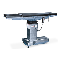
Perform the following for each X-ray top section:
1. Loosen screws securing spring-loaded spacers to X-ray top section. Position
section on table.
2. Rotate spacers so spring clips are in line when viewed from beneath tabletop
(see Figure 4-13).
3. Shift X-ray top section until mounting screw shaft on one of spring-loaded
spacers is centered in hole in X-ray top section. (A 1/16" [1.6 mm] clearance
is provided between each screw shaft and its X-ray mounting hole.)
4. Hold spacer to prevent it from rotating and tighten screw.
5. Ensure remaining spring-loaded spacer is flat against tabletop and center it
in its tabletop mounting hole, then tighten screw.
NOTE: When removing an X-ray top section, grasp it at the corners where the
spring-loaded spacers are located and lift straight up. Grasping it at the
opposite corners will cause the spacers to bind. Repeat the preceding
procedure if the spacers bind when section is lifted correctly.
6. Remove replace X-ray top section several times; X-ray top should lift freely.
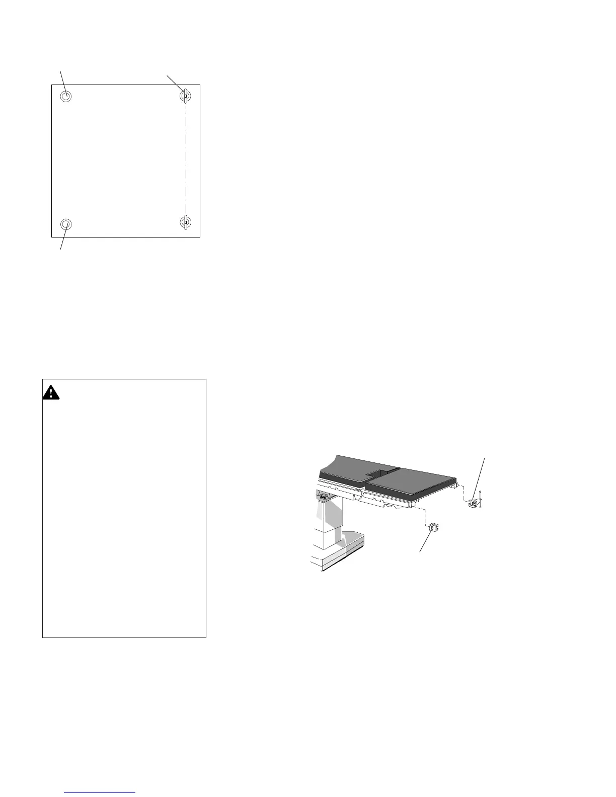
1. To install, place clamp (or socket) on side rail and lock in position with knob
(or handle) provided (see Figure 4-14).
2. To remove, loosen knob (or handle) and slide clamp (or socket) along side
rail until a notch is reached, then remove clamp (socket).
NOTE: Clamp (socket) may also be removed from end of side rail by raising
gravity stops.
Typical X-Ray Top Section
Figure 4-13. X-Ray Top
Spring Clips and Standoffs
4.6.3 General Accessories
Applied to Side Rails
WARNING – PERSONAL
INJURY HAZARD:
• When installing any table ac-
cessory, check for correct at-
tachment and tighten se-
curely (if appropriate). Do not
use worn or damaged acces-
sory. Check installation be-
fore using any accessory.
• There is a 1,000-lb (452-kg)
patient weight limit if patient
is in normal orientation and
a 500-lb (226-kg) patient
weight limit if patient is in
reversed orientation; how-
ever, the accessory load rat-
ing may be lower. Do not
exceed the accessory load
rating if it is lower than the
table rating.
Clamp
Socket
Figure 4-14. General Accessories Applied to Side Rails
Short Standoff
Spring Clip Projecting
Beyond Standoff
Short Standoff
 Loading...