For full warranty information, refer to the AMX Instruction Manual(s) associated with your Product(s).
1/09
©2009 AMX. All rights reserved. AMX and the AMX logo are registered trademarks of AMX.
AMX reserves the right to alter specifications without notice at any time.
3000 RESEARCH DRIVE, RICHARDSON, TX 75082 • 800.222.0193 • fax 469.624.7153 • technical support 800.932.6993 • www.amx.com
93-2101 REV: D
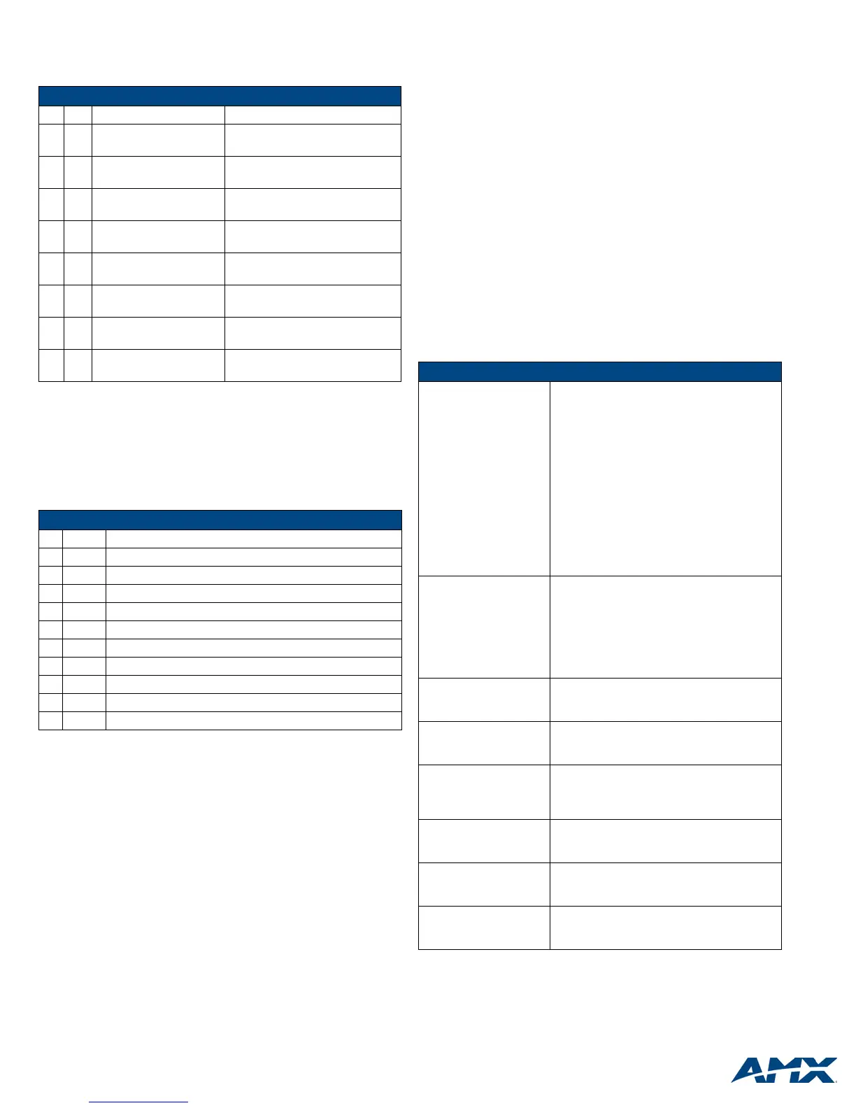
IR/Serial Connector Wiring Specifications
You can connect up to eight IR- or serial-controllable devices to the IR/Serial
connectors (ports 8-15). These connectors accept a IR emitter (CC-NIRC) that
mounts on the device's IR window, or a mini-plug (CC-NSER) that connects to the
device's control jack.
I/O Port Wiring Specifications
The I/O port responds to switch closures or voltage level (high/low) changes, or can
be used for logic-level outputs. You can connect up to eight devices to the I/O
connectors (port 16). A contact closure between GND and an I/O port is detected as
a Push. When used for voltage inputs, the I/O port detects a low (0-1.5 VDC) as a
Push, and a high (3.5-5 VDC) signal as a Release. When used for outputs, the I/O
port acts as a switch to GND and is rated at 200 mA @ 12 VDC.
The PWR pin (+12 VDC @ 200 mA) is designed as a power output for the PCS2 or
VSS2 (or equivalent). The GND connector is a common ground and is shared by all
I/O ports. The following table lists the wiring specifications for the I/O connectors.
Using the ID Button
The ID Button on the rear panel of the NXI (see Figure 1) is used in conjunction with
the NetLinx Studio software program to allow you to assign a new Device number to
the NXI.
1. Using NetLinx Studio, place the system in Identify (ID) Mode. ID Mode means
that the entire system is put on hold while it waits for an event from any NetLinx
device in the named system (for example, pushing the ID button on the NXI).
The device that generates the first event is the device that is identified.
2.
Press the ID Mode button to generate an event from the NXI and assign new
Device number in NetLinx Studio.
Device:Port:System (D:P:S)
A device is any hardware component that can be connected to an AXlink or NetLinx
(ICSNet) bus. Each device must be assigned a unique number to locate that device
on the bus. The NetLinx programming language allows numbers in the range
0-32,000. Device 0 (zero) refers to the master, and numbers greater than 32,000 are
reserved.
NetLinx requires a Device:Port:System (D:P:S) specification. This D:P:S triplet can
be expressed as series of constants, variables separated by colons, or as a DEV
structure. For example:
STRUCTURE DEV
{
INTEGER Number // Device number
INTEGER Port // Port on device
INTEGER System // System the device belongs to
}
The D:P:S notation is used to explicitly represent a device number, port and system.
For example, 128:1:0 represents the first port on the device TP on this system.
If the Port and System numbers are omitted, Port #1 (the first port) and System #0
(this system) are assumed. Here's the syntax:
NUMBER:PORT:SYSTEM
where:
• NUMBER: 16-bit integer representing the device number
• PORT: 16-bit integer representing the port number (in the range 1 through the
number of ports on the Controller or device)
• SYSTEM: 16-bit integer representing the system number (0 = this system)
NetLinx Device Number Conventions
NXI Integrated Controllers typically occupy the device number range from 5001 to
5999.
By default, all NXI’s are shipped with a virtual device ID assigned to 32,001. You
must assign a real device number (via NetLinx Studio) before use.
In NetLinx Studio, select Tools > NetLinx Diagnostics to open the NetLinx
Diagnostics dialog. Set the device number in the Device Addressing tab, using either
the Change Address or ID Mode option (see Using the ID Button).
Send_Commands
Refer to the NXI Integrated Controller Instruction Manual for detailed programming
information.
IR/Serial Connector Wiring Specifications
No. Port Signal Function
1 8 GND (-)
Signal 1 (+)
Signal GND
IR/Serial data
2 9 GND (-)
Signal 2 (+)
Signal GND
IR/Serial data
3 10 GND (-)
Signal 3 (+)
Signal GND
IR/Serial data
4 11 GND (-)
Signal 4 (+)
Signal GND
IR/Serial data
5 12 GND (-)
Signal 5 (+)
Signal GND
IR/Serial data
6 13 GND (-)
Signal 6 (+)
Signal GND
IR/Serial data
7 14 GND (-)
Signal 7 (+)
Signal GND
IR/Serial data
8 15 GND (-)
Signal 8 (+)
Signal GND
IR/Serial data
I/O Port Wiring Specifications
Pin Signal Function
1 GND Signal GND
2 I/O 1 Input/output
3 I/O 2 Input/output
4 I/O 3 Input/output
5 I/O 4 Input/output
6 I/O 5 Input/output
7 I/O 6 Input/output
8 I/O 7 Input/output
9 I/O 8 Input/output
10 12 VDC PWR
RS-232/422/485 Port Configuration Send_Commands
SET BAUD
Sets the RS-232/422/485
port's communication
parameters.
Syntax:
SEND_COMMAND <DEV>,'SET BAUD
(Baud),(Parity),(Data),(Stop) (485
DISABLE/ENABLE)'
• Baud: 150, 300, 600, 1200, 2400, 4800, 9600,
19200, 38400 (factory set default), 57600, 76800,
115200, 230400
• Parity: N (none), O (odd), E (even), M (mark), S
(space)
• Data: 7 or 8 data bits
• Stop: 1 or 2 stop bits
• 485 Disable: Disables RS-485 mode and enables
RS-422
• 485 Enable: Enables RS-485 mode and disables
RS-422
TSET BAUD
Temporarily sets the
RS-232/422/485 port's
communication parameters.
Syntax:
SEND_COMMAND <DEV>,'TSET BAUD
(Baud),(Parity),(Data), (Stop) (485
DISABLE/ENABLE)'
TSET BAUD works the same as SET BAUD, except
that the changes are not permanent, and the previ-
ous values will be restored if the power is cycled on
the device.
HSOFF
Disables hardware hand-
shaking (default).
Syntax:
SEND_COMMAND <DEV>,'HSOFF'
HSON
Enables RTS and CTS
hardware handshaking.
Syntax:
SEND_COMMAND <DEV>,'HSON'
CAROFF
Disables the carrier signal
until a CARON command is
received.
Syntax:
SEND_COMMAND <DEV>,'CAROFF'
CARON
Enables carrier signals
(default setting).
Syntax:
SEND_COMMAND <DEV>,'CARON'
ZAP LOW
Deletes all IR data stored in
the NXI ports 8-11.
Syntax:
SEND_COMMAND <DEV>, 'ZAP LOW'
ZAP HIGH
Deletes all IR data stored in
the NXI ports 12-15.
Syntax:
SEND_COMMAND <DEV>, 'ZAP HIGH'

 Loading...