Quick Start Guide
NI-2100 NetLinx Integrated Controller
For more detailed installation, configuration, programming, file transfer, and
operating instructions, refer to the NetLinx Integrated Controllers (NI-2100,
NI-3100, and NI-4100 Series) Instruction Manual, available online at
www.amx.com.
Overview
The NI-2100 unit (FG2105-04) is geared to meet the specific control and
automation needs of a single room environment, these needs may include
the integration of a limited number of video players, projectors, lighting,
thermostats, and other electronic equipment. The NI-2100 provides support
for 3 RS-232/RS-422/RS-485 Ports, 4 IR/Serial Output ports,
4 Digital Input/Output ports, and 4 Relays. The NI-2100 can be upgraded to
provide 1 ICSHub and 2 ICSNet ports by either installing the optional
ICSNet daughter card (FG2105-10) or purchasing this upgrade as an
included feature of the NI-2100 Kit (FG2105-14).
ATTENTION!
Verify you are using the latest NI firmware for the on-board Master. Verify
you are using the latest version of NetLinx Studio (available for download
from www.amx.com).
Specifications
Ethernet Ports used by the NI Controller
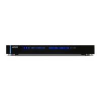
FIG. 1 NI-2100 NetLinx Integrated Controller (front view)
NI-2100 Specifications
Dimensions
(HWD):
• 3.47" x 17.00" x 3.47" (8.81 cm x 43.18 cm x 8.82 cm)
• 2 rack units high
Power
Requirement:
• 700 mA @ 12 VDC
Memory: • 64 MB SDRAM
• 1 MB Non-volatile (NV) SRAM
Compact Flash: • 128 MB Card (upgradeable) (refer to the Other AMX Equipment
section for more information)
• Refer to the NetLinx Integrated Controllers (NI-2100, NI-3100,
and NI-4100 Series) Instruction Manual for more information.
Weight: • 4.50 lbs (2.04 kg)
Enclosure: • Metal with black matte finish
Certifications: • FCC Part 15 Class B, CE, and IEC 60950
Front Panel
Components:
• LINK/ACT: Green LED blinks when the Ethernet cables are
connected and terminated correctly. Also blinks when receiving
Ethernet data packets.
• Status: Green LED blinks to indicate that the system is
programmed and communicating properly.
• Output: Red LED blinks when the Controller transmits data, sets
channels On and Off, sends data strings, etc.
• Input: Yellow LED blinks when the Controller receives data from
button pushes, strings, commands, channel levels, etc.
• RS-232/422/485 LEDs: 3 sets of red and yellow LEDs light to
indicate the rear DB9 Ports 1 - 3 are transmitting or receiving
RS-232, 422, or 485 data
• Relay LEDs: Four red LEDs light to indicate the rear relay
channels 1 - 4 are active (closed). These LEDs reflect the state of
the relay on Port 4.
• IR/Serial LEDs: Four red LEDs light to indicate the rear IR/Serial
channels 1 - 4 are transmitting control data on Ports 5 - 8. LED
indictor for each IR port remains lit for the length of time that
IR/Serial data is being generated.
• I/O LEDs: Four yellow LEDs light when the rear I/O channels
1 - 4 are active. LED indicator for each I/O port reflects the state
of that particular port.
• Rack-mount brackets: Provides an installation option for the
Integrated Controller to be mounted into an equipment rack,
when used with the Installation Kit (KA2105-01).
NI-2100 Specifications (Cont.)
Rear Panel
Connectors:
• RS-232/422/485 (Ports 1 - 3): Three RS-232/422/485 control
ports using DB9 (male) connectors with XON/XOFF (transmit
on/transmit off), CTS/RTS (clear to send/ready to send), and
300-115,200 baud.
• ICSNet: Two RJ-45 connectors for ICSNet interface
(provided by ICSNet daughter card).
• ICSHub Out: RJ-45 connector provides data to a Hub connected
to the Controller (provided by ICSNet daughter card).
•Relay (Port 4): 4-channel single-pole single throw relay ports with
each relay being independently controlled and supporting up to
4 independent external relay devices.
• Digital I/O (Port 9): 4-channel binary I/O port for contact closure
with each input being capable of voltage sensing. Input format is
software selectable with interactive power sensing for IR ports.
•IR/Serial (Ports 5 - 8): Four IR/Serial control ports support
high-frequency carriers of up to 1.142 MHz with each output
being capable of two electrical formats: IR or Serial. Four
IR/Serial data signals can be generated simultaneously. IR ports
support data mode (at limited baud rates and wiring distances).
• Program Port: RS-232 DB9 connector (male) can be connected to
a DB9 port on a PC. This connector can be used with serial and
NetLinx programming commands, as well as other DB9 capable
devices, to both upload/download information from the NetLinx
Studio program.
• Configuration DIP Switch: Sets the communication parameters for
the Program port.
• ID Pushbutton: Sets the NetLinx ID (Device only) assignment for
the device.
• Ethernet Port: LEDs show communication activity, connection
status, speeds, and mode information:
SPD (speed) - Yellow LED lights On when the connection speed
is 100 Mbps and turns Off when the speed is 10 Mbps.
L/A (link/activity) - Green LED lights On when the Ethernet cables
are connected and terminated correctly, and blinks when
receiving Ethernet data packets.
• AXlink LED: Green LED indicates the state of the AXlink port.
• AXlink Port: 4-pin 3.5 mm mini-Phoenix (male) connector that
provides data and power to external control devices.
• Power Port: 2-pin 3.5 mm mini-Phoenix (male) connector.
Included
Accessories:
• 2-pin 3.5 mm mini-Phoenix (female) PWR connector (41-5025)
• 4-pin 3.5 mm mini-Phoenix (female) AXlink connector (41-5047)
• 6-pin 3.5 mm mini-Phoenix female I/O connector (41-5063)
• 8-pin 3.5 mm mini-Phoenix female Relay connector (41-5083)
• Installation Kit (KA2105-01):
8-pin Relay Common Strip
Four rack mount screws
Four washers
• Quick Start Guide
• Two CC-NIRC IR Emitters
• Two removable rack ears (62-2105-07)
Other AMX
Equipment:
• 2-pin 3.5 mm mini-Phoenix male connector (41-5026)
• CSB Cable Support Bracket (FG517)
• CC-NIRC IR cables (FG10-000-11)
• CC-NSER IR/Serial cables (FG10-007-10)
• ICSNet daughter card (FG2105-10)
• NCK, NetLinx Connector Kit (FG2902)
• STS, Serial To Screw Terminal (FG959)
• Upgrade Compact Flash (factory programmed with firmware):
NXA-CF2NI256M - 256 MB compact flash card (FG2116-47)
NXA-CF2NI512M - 512 MB compact flash card (FG2116-48)
NXA-CF2NI1G - 1 GB compact flash card (FG2116-49)
Ethernet Ports Used
Port type Description Standard Port #
FTP The on-board Master has a built-in FTP server. 21/20 (TCP)
SSH The SSH port uses SSL as a mechanism to configure
and diagnose a NetLinx system. This port value is
used for secure Telnet communication.
Note: We currently ONLY support SSH version 2.
22 (TCP)
Telnet The NetLinx Telnet server provides a mechanism to
configure and diagnose a NetLinx system.
23 (TCP)
HTTP The Master has a built-in web server that complies
with the HTTP 1.0 specification and supports all of
the required features of HTTP v1.1.
80 (TCP)
HTTPS/SSL The Master has a built-in SSL protected web server. 443 (TCP)
ICSP Peer-to-peer protocol used for both Master-to-Master
and Master-to-device communications.
1319 (UDP/TCP)
integration!
Solutions
The feature on the Master uses, by default, port
10500 for the XML based communication protocol.
This port is connected to by the client web browser’s
JVM when integration! Solutions control pages are
retrieved from the on-board Master’s web server.
10500 (TCP)