EasyManua.ls Logo

AMX NetLinx NI-700 - User Manual

AMX NetLinx NI-700
2 pages
Print Icon
To Next Page IconTo Next Page
Loading...
Quick Start Guide
NI-700
NetLinx Integrated Controller
For more detailed installation, configuration, programming, file transfer, and
operating instructions, refer to the NetLinx Integrated Controllers Instruction
Manual, available on-line at www.amx.com.
Overview
The NI-700 unit (FG2105-03) is geared to meet the specific control and
automation needs of a single room environment, where both price and
functionality are the driving requirement. This product is configured to control a
limited number of video players, projectors, lighting, thermostats, and other
electronic equipment. The NI-700 provides support for 1 IR/Serial Output port,
2 RS-232/RS-422/RS-485 ports, 4 Digital Input/Output ports, and 1 IR RX port.
ATTENTION!
When working with the NI-700 Integrated Controller, verify you are using the
latest version of NetLinx Studio v 2.2 build 78 or higher (available for download
from www.amx.com).
Port Assignment and Functionality
Ethernet Ports used by the NI Controller
FIG. 1 NI-700 NetLinx Integrated Controller (front and rear views)
NI-700 Specifications
Dimensions (HWD): 1.58" x 5.54" x 5.12" (4.01 cm x 14.10 cm x 13.00 cm)
1 rack unit high
Power: 280 mA @ 12 VDC
Memory: •32 MB SDRAM
16 MB Flash chip
512 Kb of Non-volatile SRAM
Refer to the NetLinx Integrated Controllers Instruction Manual for more
information.
Microprocessor: 304 MIPS using a PowerPC™ processor
Weight: 1.30 lbs (0.59 kg)
Enclosure: Metal with black matte finish
Front Panel: Program Port: RS-232 DB9 connector (male) can be connected to a
DB9 port on a PC. This port can be used with both Serial and NetLinx
commands.
Configuration DIP Switch: Use this DIP switch to set the communication
parameters for the Program port.
IR RX LED: Red LED lights to indicate when IR data is being received
via the rear IR RX port.
IR LED: Red LED lights to indicate transmission of IR or Serial data
via the rear IR port.
I/O LEDs: Four yellow LEDs light when the rear I/O channels 1-4 are
active. LED indicator for each I/O port reflects the state of that
particular port.
Serial LEDs: Two sets of red and yellow LEDs light to indicate the rear
DB9 Ports 1 & 2 are transmitting or receiving RS-232, 422, or 485
data. These LEDs do not reflect changes in either the RTS or CTS
when hardware handshaking is used.
LINK/ACT: Green LED lights when the Ethernet cable is connected and
an active link is established. This LED also blinks when receiving
Ethernet data packets.
Status: Green LED lights to indicate that the system is programmed
and communicating properly.
Output: Red LED lights when the Controller transmits data, sets
channels On and Off, sends data strings, etc.
Input: Yellow LED lights when the Controller receives data from button
pushes, strings, commands, channel levels, etc.
ID Pushbutton: Sets the NetLinx ID (Device only) assignment for the
device.
(front)
(rear)
NI-700 Specifications (Cont.)
Rear Panel: RS-232/422/485 (Ports 1 & 2): Two RS-232/422/485 control ports
using DB9 (male) connectors with XON/XOFF (transmit on/transmit
off), CTS/RTS (clear to send/ready to send), and 300-115,200 baud.
IR RX (Port 5): This single port is used to connect one or more
(8 maximum) IRX-SM+ swivel mount or IRX-DM+ Decora mount IR
receivers.
The IR RX port functions using AMX IR codes (38 KHz and 455 KHz)
and works ONLY with AMX IR Receivers such as the IRX-DM+ and
IRX-SM+.
Digital I/O (Port 4): Four-channel binary I/O port for contact closure
with each input being capable of voltage sensing. Input format is
software selectable with interactive power sensing for IR ports.
•IR/Serial (Port 3): This single port is capable of generating IR with the
use of an IR emitter (while in IR mode). This port can support
high-frequency carriers of up to 1.142 MHz and can also generate IR
with no carrier frequency.
AXlink LED: One green LED indicates the state of the AXlink port.
AXlink port: 4-pin 3.5 mm mini-Phoenix (male) connector provides data
and power to external control devices.
Ethernet port: LEDs show communication activity, connections,
speeds, and mode information:
L/A-link/activity - Green LED lights On when the Ethernet cables are
connected and terminated correctly and blinks when receiving
Ethernet data packets.
SPD-speed - Yellow LED lights On when the connection speed is
100 Mbps and turns Off when the speed is 10 Mbps.
Power port: 2-pin 3.5 mm mini-Phoenix (male) connector
Included
Accessories:
NI-700 Quick Start Guide (93-2105-03)
One 6-pin 3.5 mm mini-Phoenix female I/O connector (41-5063)
One 4-pin 3.5 mm mini-Phoenix female AXlink connector (41-5047)
One 2-pin 3.5 mm mini-Phoenix female PWR connector (41-5025)
One CC-NIRC IR Emitter (FG10-000-11)
OpenSSL Warranty and Licensing Information (93-2105-05)
Optional
Accessories:
2-pin Black Male Phoenix Connector (3.5mm) (41-5026)
AC-RK Accessory Rack Kit (FG515)
CC-NIRC IR cables (FG10-000-11)
CC-NSER IR/Serial cables (FG10-007-10)
CSB Cable Support Bracket (FG517)
PSN2.8: Power supply (FG423-17)
PSN4.4: Power supply(FG423-45)
PSN6.5: Power supply (FG423-41)
STS, Serial To Screw Terminal (FG959)
Surface Mount Bracket Accessory (FG525)
NetLinx Port Assignments
Port ICSP Port #
Serial Port 1 1
Serial Port 2 2
IR Port 3
I/O Port 4
IR RX Port 5
Ethernet Port Usage
Port type Description Standard Port #
ICSP Peer-to-peer protocol used for both Master-to-Master and
Master-to-device communications.
1319 (UDP/TCP)
Telnet The NetLinx Telnet server provides a mechanism to
configure and diagnose a NetLinx system.
23 (TCP)
HTTP The Master has a built-in web server that complies with the
HTTP 1.0 specification and supports all of the required
features of HTTP v1.1.
80 (TCP)
HTTPS The Master has a built-in SSL protected web server. 443 (TCP)
FTP The on-board Master has a built-in FTP server that
conforms to RFC959.
21/20 (TCP)
Internet Inside The Internet Inside feature the Master uses, by default, is
port 10500 for the XML based communication protocol.
This port is connected to by the client web browsers JVM
when Internet Inside control pages are retrieved from the
on-board Masters web server.
10500 (TCP)
Get other manuals https://www.bkmanuals.com
Question and Answer IconNeed help?

Do you have a question about the AMX NetLinx NI-700 and is the answer not in the manual?

Summary

NI-700 Specifications

Dimensions

Physical dimensions of the NI-700 unit.

Power Requirements

Electrical power consumption details for the NI-700.

Memory Specifications

Details on SDRAM, Flash, and SRAM capacity.

Microprocessor

Information on the NI-700's central processing unit.

Weight

The total weight of the NI-700 unit.

Enclosure Type

Description of the NI-700's physical casing material and finish.

Front Panel Components

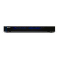
Details about the connectors and indicators on the front panel.

Rear Panel Components

Details about the connectors and indicators on the rear panel.

Included Accessories

List of items provided with the NI-700 unit.

Optional Accessories

List of optional accessories available for the NI-700.

Port Assignment and Functionality

Ethernet Ports Usage

Connections and Wiring

Power Connection

Instructions for connecting power to the NI-700.

RS-232;422;485 Wiring

Pinout and wiring specifications for serial ports.

Ethernet Connector

Details on connecting to the 10/100 Base-T Ethernet port.

Program Port Baud Rate Settings

Configuration of DIP switches for the Program Port baud rate.

Setting the Configuration DIP Switch

Procedure for setting the Program Port DIP switch.

Preparing for Communication

Steps to prepare the NI-700 for communication via NetLinx Studio.

Communicating via Ethernet

Steps for establishing Ethernet communication with the controller.

Overview

The AMX NI-700 NetLinx Integrated Controller is a versatile control and automation solution designed for single-room environments where both cost-effectiveness and robust functionality are paramount. This device is engineered to manage a diverse array of electronic equipment, including video players, projectors, lighting systems, thermostats, and other control devices, making it an ideal central hub for integrated room control.

Function Description

At its core, the NI-700 serves as a central processing unit for automation tasks. It facilitates communication with various devices through a comprehensive set of ports. The controller supports one IR/Serial Output port, two RS-232/RS-422/RS-485 ports, four Digital Input/Output ports, and one IR RX port. This array of connectivity allows the NI-700 to send commands to and receive feedback from a wide range of controlled devices, enabling seamless automation and integration.

The RS-232/422/485 ports are designed for serial communication, offering flexible control over devices that utilize these protocols. These ports support various baud rates, from 300 to 115,200 baud, and include XON/XOFF and CTS/RTS handshaking for reliable data transmission. This makes them suitable for controlling professional-grade audio/video equipment, lighting systems, and other serial-controlled devices.

The IR/Serial Output port is particularly useful for controlling devices via infrared signals, such as televisions, projectors, and other consumer electronics. It can generate IR signals with high-frequency carriers up to 1.142 MHz, or without a carrier frequency, providing broad compatibility. When configured for serial mode, this port can also send serial commands, adding to its versatility.

The Digital I/O ports are designed for contact closure applications, allowing the NI-700 to interact with simple on/off devices or sensors. Each input is capable of voltage sensing, and the input format is software-selectable, offering flexibility in how these ports are used. This is useful for integrating with motion sensors, door contacts, or other binary input devices, as well as for controlling relays or other simple output devices.

The IR RX (Infrared Receive) port is dedicated to receiving IR signals from AMX IR receivers, such as the IRX-SM+ swivel mount or IRX-DM+ Decora mount receivers. This allows the NI-700 to receive commands from handheld IR remotes or other IR-emitting devices, enabling user interaction with the integrated system. The port functions exclusively with AMX IR codes (38 KHz and 455 KHz), ensuring reliable communication within the AMX ecosystem.

An AXLink port is also included, providing data and power to external control devices within the AMX AXLink network. This simplifies wiring and integration for compatible AMX accessories.

The Ethernet port is a critical component for network connectivity, supporting 10/100 Base-T communication. This allows the NI-700 to be integrated into a local area network (LAN), enabling IP-based control, remote management, and communication with other network-enabled devices. The NI-700 features a built-in web server for HTTP and HTTPS access, an FTP server for file transfers, and supports Telnet for configuration and diagnostics. It also uses a peer-to-peer protocol (ICSP) for master-to-master and master-to-device communications, and a proprietary "Internet Inside" feature for XML-based communication with client web browsers.

Usage Features

The NI-700 is designed for straightforward setup and operation, although it requires the use of NetLinx Studio software for programming and configuration. The device features a front panel with various LEDs and a configuration DIP switch, providing visual feedback and initial setup options.

The front panel LEDs offer immediate status indicators:

  • IR RX LED (Red): Lights up when IR data is being received via the rear IR RX port, confirming active IR input.
  • IR LED (Red): Lights up when IR or Serial data is being transmitted via the rear IR port, indicating active output.
  • I/O LEDs (Yellow): Four LEDs that light up when the rear I/O channels 1-4 are active, reflecting the state of each I/O port.
  • Serial LEDs (Red and Yellow): Two sets of LEDs indicate when the rear DB9 Ports 1 & 2 are transmitting (red) or receiving (yellow) RS-232, 422, or 485 data. These LEDs do not reflect RTS or CTS handshaking changes.
  • LINK/ACT (Green): Lights up when the Ethernet cable is connected and an active link is established, and blinks when receiving Ethernet data packets, indicating network activity.
  • STATUS (Green): Lights up to indicate that the system is programmed and communicating properly.
  • Output (Red): Lights up when the Controller transmits data, sets channels On and Off, or sends data strings.
  • Input (Yellow): Lights up when the Controller receives data from button pushes, strings, commands, or channel levels.

A Configuration DIP Switch on the front panel allows for setting the baud rate for the Program Port, which is used for initial setup and programming via a PC. The default baud rate is 38,400 bps. This switch also includes options for activating/deactivating the Program Run Disable Mode.

The ID Pushbutton on the front panel is used to set the NetLinx ID (Device only) assignment for the device, simplifying device identification within a larger NetLinx system.

The NI-700 is typically powered by a standard PSN power supply, connected via a 2-pin 3.5 mm mini-Phoenix connector on the rear panel.

Maintenance Features

While the NI-700 is designed for reliable operation, certain aspects facilitate maintenance and troubleshooting:

  • Firmware Updates: The device requires the latest version of NetLinx Studio software (v 2.2 build 78 or higher) for optimal performance and compatibility. Regular checks for software updates are recommended to ensure access to new features, bug fixes, and improved stability.
  • Diagnostic Tools: NetLinx Studio provides diagnostic tools, such as the "Online tab" for refreshing the system and "Diagnostics > Network Address" for managing IP settings. These tools are crucial for verifying communication, assigning system values, and troubleshooting network connectivity.
  • Reboot Functionality: The ability to reboot the Master Controller via NetLinx Studio ("Tools > Reboot the Master Controller") allows for applying configuration changes and resolving minor operational issues without physically accessing the device.
  • LED Indicators: The comprehensive set of front and rear panel LEDs provides immediate visual feedback on the device's status, communication activity, and port states. These indicators are invaluable for quick troubleshooting, allowing users to identify potential issues at a glance (e.g., lack of network link, no IR signal, or communication errors).
  • Documentation: The NetLinx Integrated Controllers Instruction Manual, available online, serves as a comprehensive resource for detailed installation, configuration, programming, file transfer, and operating instructions. This manual is essential for both initial setup and ongoing maintenance.
  • Network Configuration: The NI-700 supports both DHCP for automatic IP address assignment and static IP configuration, offering flexibility in network deployment. The ability to set the Ethernet mode to "AUTO negotiate" ensures compatibility with various network environments, although it specifically restricts manual speed/duplex settings to avoid errors.
  • Physical Enclosure: The device is housed in a metal enclosure with a black matte finish, providing durability and a professional appearance suitable for rack mounting (1 rack unit high).

In summary, the AMX NI-700 NetLinx Integrated Controller is a robust and flexible solution for single-room automation, offering extensive connectivity, user-friendly diagnostic indicators, and comprehensive software support for efficient management and maintenance.

AMX NetLinx NI-700 Specifications

General IconGeneral
Power SupplyExternal Power Supply
Operating Voltage12 VDC
Network Interfaces10/100Base-T Ethernet
IR PortsTwo (2)
RS-232/422/485 PortsTwo (2)
IR/Serial Ports4
Relay Ports4
I/O Ports8
Operating Temperature0° to 40° C
Dimensions8.5 in
Power Consumption10W maximum

Related product manuals