For full warranty information, refer to the AMX Instruction Manual(s) associated with your Product(s).
060-004-2946 05/06
©2006 AMX. All rights reserved. AMX and the AMX logo are registered trademarks of AMX.
AMX reserves the right to alter specifications without notice at any time.
3000 RESEARCH DRIVE, RICHARDSON, TX 75082 • 800.222.0193 • fax 469.624.7153 • technical support 800.932.6993 • www.amx.com
93-2105-14
REV: B
Connections and Wiring
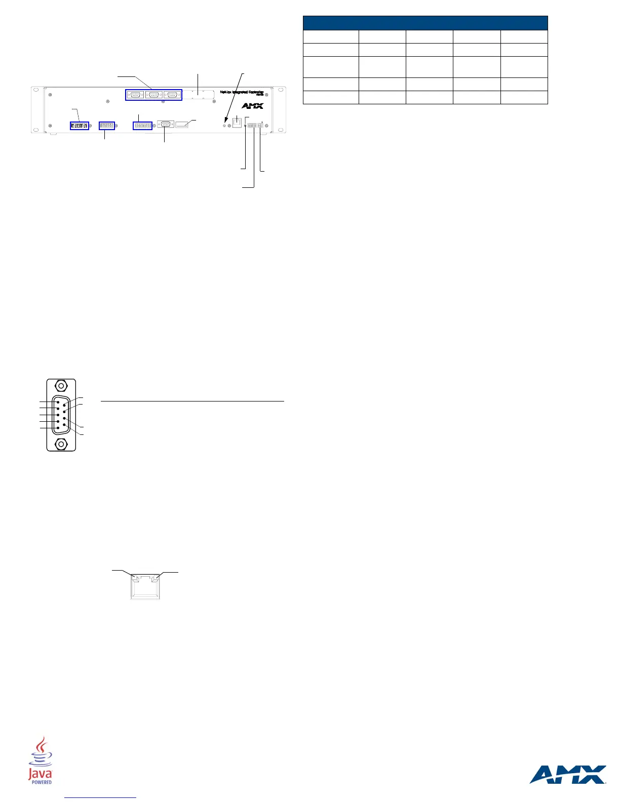
FIG. 2 shows the layout of the connectors and components located on the
rear of the NI-2100 NetLinx Integrated Controller.
Wiring a power connection
Use a 12 VDC-compliant power supply to provide power to the Integrated
Controller through the rear 2-pin 3.5 mm mini-Phoenix. Use the power
requirements information listed in the Specifications table to determine the
power draw.
The incoming PWR and GND cable from the PSN power supply must be
connected to their corresponding locations within the PWR connector.
Refer to the NetLinx Integrated Controllers Instruction Manual for more
detailed wiring connection information.
RS-232/422/485 wiring connector information
FIG. 3 shows the pinout and wiring specification information for the rear
RS-232/RS-422/RS-485 (DB9) Device Ports. These ports support most
standard serial mouse control devices and RS-232 communication
protocols for PC data transmission (NI-2100 uses Ports 1 - 3).
RJ-45 Connections
Use a standard CAT5 Ethernet cable to provide communication between the
Integrated Controller and external NetLinx devices.
Ethernet 10/100 Base-T Connector
The Ethernet cable provides 10/100 network connectivity between the
panel and the NetLinx Master (FIG. 4).
Baud Rate Settings
The Program Port DIP switch is located on the rear of the device. Use this
DIP switch to set the baud rate for the Program Port, according to the
settings shown in the following table. Make sure the baud rate you set
matches the baud rate on your PC's NetLinx COM Settings before
programming the unit. By default, the baud rate is set to 38,400 (bps).
Note: DIP switch 1 activates/deactivates the Program Run Disable
Mode. DIP Switches 2,3, and 4 must remain OFF at all times.
Preparing the NI-2100 for Serial Communication
1. Launch NetLinx Studio 2.x (default location is Start > Programs >
AMX Control Disc > NetLinx Studio 2 > NetLinx Studio 2).
2. Select Settings > Master Communication Settings, from the Main
menu, to open the Master Communication Settings dialog box.
3. Click the Communications Settings button to open the
Communications Settings dialog.
4. Click the NetLinx Master radio button (from the Platform Selection
section) to indicate you are working with a NetLinx Master.
5. Click the Serial radio button (from the Transport Connection Option
section) to indicate you are connecting to the Master via a COM port.
6. Click the Edit Settings button (on the Communications Settings
dialog) to open the Serial Settings dialog and set the COM port
parameters (used to communicate to the NetLinx Master).
7. Click the OK button three times to return to the main application.
8. Right-click the Online Tree tab entry and select Refresh System.
9. Assign a System Value by using Diagnostics > Device Addressing
from the Main menu.
10. Enable the Change System selection by clicking on it and then
enter the current and new System values.
11. Click the Change Device/System Number button and when finished
click Done.
12. Select Tools > Reboot the Master Controller to access the Reboot
the Master dialog, then click Reboot to restart the Master and
incorporate any changes.
13. Once the dialog replies with "Reboot of system complete", click
Done and then click the OnLine Tree tab in the Workspace window
to view the devices on the System.The default System value is one.
14. Right-click on the Empty Device Tree/System entry and select
Refresh System to re-populate the list.
Configuring the NI-2100 for Ethernet Communication
Before continuing, complete the COM port steps above.
1. Connect an Ethernet cable to the unit’s rear Ethernet connector.
2. Select Diagnostics > Network Address from the Main menu and
enter the System, Device (0 for a Master), and Host Name
information.
3. To configure the Address:
• Use a DHCP Address by selecting the Use DHCP radio button, then
click the GET IP button (to obtain a DHCP Address from the DHCP
Server), click the SET IP Information button (to retain the new
address), and then finish the process by clicking the Reboot Master
> OK buttons.
• Use a Static IP Address by selecting the Specify IP Address radio
button, enter the IP parameters into the available fields, then click the
SET IP Information button (to retain the pre-reserved IP Address to
the Master), and then click the Reboot Master > OK buttons to finish
the process.
4. Repeat steps 1 - 5 from the previous section but rather than selecting
the Serial option, choose TCP/IP and edit the settings to match the
IP Address you are using (whether Static or IP).
5. Click on the Authentication Required radio box (if the Master is
secured) and press the User Name and Password button to enter a
valid username and password being used by the secured Master.
6. Click the OK button three times to return to the main application.
FIG. 2
NI-2100 rear connectors and components
FIG. 3 RS-232/422/485 DB9 (male) connector pinouts
FIG. 4 Layout of Ethernet LEDs
AXlink LED
Relays
RS-232/422/485 (Ports 1-3)
I/O (Port 9)
IR/Serial (Ports 5-8)
Rear
Program port
DIP
switch
(green)
ID Pushbutton
(Port 4)
Ethernet
AXlink
port
PWR
ICSNet cover plate
5
4
3
2
1
9
8
7
6
Male
DB9 Serial Port pinouts (male connector)
Pin 2: RX signal
Pin 3: TX signal
PIN 5: GND
Pin 7: RTS
Pin 8: CTS
RS-232
Pin 1: RX -
Pin 4: TX +
PIN 5: GND
Pin 6: RX +
Pin 9: TX -
RS-422
Pin 1: A (strap to 9)
Pin 4: B (strap to 6)
PIN 5: GND
Pin 6: B (strap to 4)
Pin 9: A (strap to 1)
RS-485
SPD - Speed LED lights (yellow) when
and turns Off when the speed
is 10 Mbps.
the connection speed is 100 Mbps
L/A - Link/Activity LED lights
(green) when the Ethernet
cables are connected and
terminated correctly.
Baud Rate Settings
Baud Rate Position 5 Position 6 Position 7 Position 8
9600 bps OFF ON OFF ON
38,400 bps
(default)
OFFONONON
57,600 bps ON OFF OFF OFF
115,200 bps ON ON ON ON

 Loading...