Rev 13 Nov 2013 01:51 | Page 3
Design and Integration Files
Schematics, layout files, bill of materials <Coming Soon>
●
Equipment Needed
Analog signal source(s) and antialiasing filter(s)
●
Sample clock source (if not using the on-board crystal oscillator)
●
Switching power supply (6.0V, 2.5A) for AD9249-65EBZ
●
Switching power supply (12V, 3,3A) for HSC-ADC-EVALDZ
●
PC running Windows®
●
USB 2.0 port
●
AD9249-65EBZ board
●
HSC-ADC-EVALDZ FPGA-based data capture kit
●
Getting Started
This section provides quick start procedures for using the AD9249-65EBZ board. Both the default and
optional ADC settings are described.
Configuring the Board
Before using the software for testing, configure the evaluation board as follows:
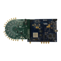
Connect the evaluation board to the data capture board, as shown in Figure 1.1.
On the ADC evaluation board, confirm that the jumpers are installed as shown in Figure 2.2.
Connect one 6V, 2.5A switching power supply (such as the CUI, Inc., EPS060250UH-PHP-SZ that is3.
supplied) to the AD9249-65EBZ.
Connect the 12V, 3.3A switching power supply to the HSC-ADC-EVALDZ board.4.
Connect the HSC-ADC-EVALDZ board (P702) to the PC using a USB cable.5.
On the ADC evaluation board, use a clean signal generator with low phase noise to provide an6.
input signal to the desired channel(s). Use a shielded, RG-58, 50Ω coaxial cable (optimally 1 m or
shorter) to connect the signal generator. For best results, use a narrow-band, band-pass filter with
50Ω terminations and an appropriate center frequency. (Analog Devices, Inc. uses TTE, Allen
Avionics, and K&L band-pass filters.)
Evaluation Board Hardware
 Loading...