AN-583 Application Note
Rev. D | Page 2 of 4
TEST EQUIPMENT SETUP
The recommended equipment and configuration is shown in
Figure 1. A low noise audio generator with a smooth output
adjustment range of 50 μV to 50 mV is a suitable signal source.
A 40 dB pad is useful to reduce the level of most generators by
100´ to simulate microphone levels. The input voltmeter can be
connected before the pad and only needs to go down to 10 mV.
The output voltmeter must go up to 2 V. The oscilloscope is
used to verify that the output is sinusoidal, that no clipping
occurs in the buffer, and that the noise gating threshold is set.
OSCILLOSCOPE
AC VOLTMETERAC VOLTMETER
SIGNAL
GENERATOR
SSM2167
EVALUATION
BOARD
02728-001
Figure 1. Test Equipment Setup
CONNECTIONS
Connect power, ground, input, and output as described in the
Basic Connections and Setup section.
TEST SETUP
To confirm the operation of the board and test setup, first put
JP4 in the 1:1 position and JP5 in the −55 dB position. With
power on, adjust the generator for an input level of 15 mV,
1 kHz. The output meter should indicate approximately
100 mV. If it does not, check the setup.
LISTENING
Connect a microphone to the SSM2167 and listen to the results.
Ensure proper power for the microphone by following instructions
in the Basic Connections and Setup section. Experiment with
the settings to hear how the results change. The compression
ratio keeps the output steady over a range of source to microphone
distances, and the noise gate keeps the background sounds subdued.
SETTING THE NOISE GATE THRESHOLD
The SSM2167 evaluation board provides three different preset
values of noise gate threshold. Experiment with these values by
varying the gate. The SSM2167 evaluation board also provides
landing pads for a custom value that can be extrapolated from
the specifications table in the SSM2167 data sheet, or the noise
gate vs. R
GATE
figure the SSM2167 data sheet. Using more than
5 kΩ is not recommended because extremely low noise gate
thresholds may approach the noise floor of the system.
The highest setting (−48 dB) is recommended to start an evaluation.
If the input signal is not sufficient to surpass the threshold,
lower the setting. In most applications, the input signal easily
overcomes this setting. If the gate is set too low, the background
noise is amplified well into the audible range. By examining the
function (see the general input/output characteristics figure in
the SSM2167 data sheet), the maximum gain of the device can
be determined when the input signal is at the noise gate threshold.
The dashed line on the transfer function represents unity gain;
the distance between the dashed line and the solid line represents
the VCA gain.
ADJUSTING THE COMPRESSION RATIO
The SSM2167 evaluation board provides three different settings
for the compression ratio in the same manner as the noise gate
threshold. Experiment with different compression ratios to
determine what sounds best in a given system; starting with a
2:1 ratio is recommended. High compression ratios exaggerate
the effect of the noise gate because the compression ratio
determines the gain at the noise gate, as shown in the output vs.
input characteristics figure in the SSM2167 data sheet. Use
compression of 10:1 only in systems where the noise floor is
well below the noise gate. Most systems require between 2:1
and 5:1 compression for best results.
LISTENING TEST
The final step in evaluating the SSM2167 is a listening test.
The improvement in vocal clarity can be heard by recording
the SSM2167 output or listening to it live. Ideally, connect the
SSM2167 evaluation board to an existing system. The impact
of the compression is demonstrated by shorting out RCOMP
(R9 through R12). When the RCOMP resistor is shorted, the
VCA reverts to the audible 1:1 compression setting, which does
not affect the noise gate or limiting settings. The effect of
turning off the compression is most noticeable when the input
signal is between −50 dBV and −40 dBV. Evaluating the SSM2167
within the end application also gives the best indication of how
high the noise gate threshold should be set. The noise level of
the system is greatly influenced by the design of the system,
including cooling fans, hard drives, handling, and other sources
of acoustic noise.
Listening tests are the most critical part of an evaluation. Because
test equipment and signal generators do not represent audio
signals well, listening is the best way to evaluate the benefits of
the SSM2167. The SSM2167 evaluation board makes it easy to
implement the SSM2167 and to pick appropriate application
settings. The end result is a noticeable improvement in signal
clarity and a system that is easy for customers to use.
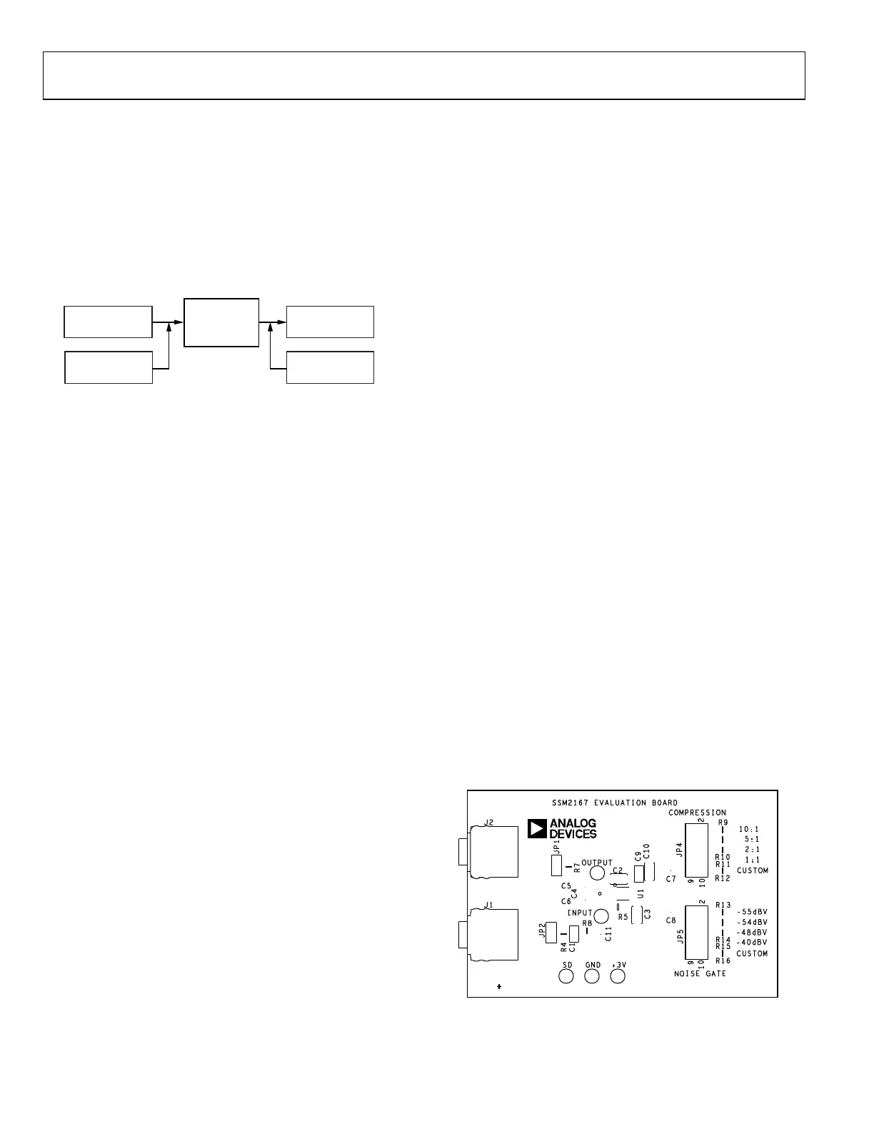
02728-002
Figure 2. SSM2167 Evaluation Board; Top Layer Including Component
Identification and Placement

 Loading...


