2) PUSHER MOTOR ERROR [E.41], PUSHER SENSOR ERROR [E.41]
▶SOLUTION : PUSHER MOTOR ERROR [E.41]
1 HOW TO TEST TEST MODE → PUSHER MOTOR TEST→ SELECT BUTTON →SHOOTING button
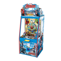
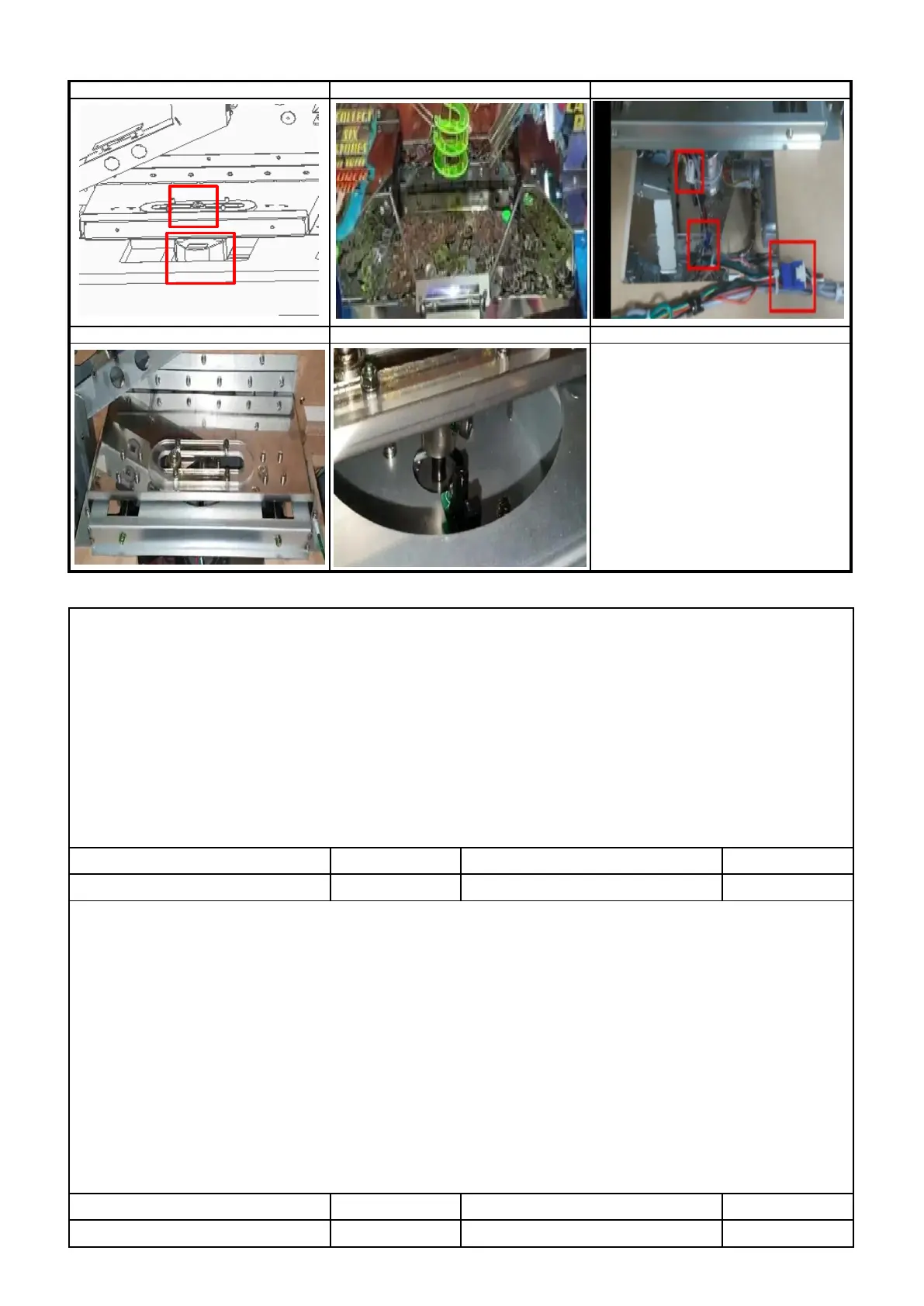
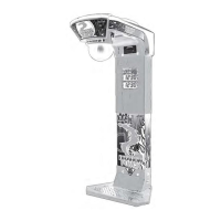
2 Check if tokens, cards, balls, side token are jamming the pusher plate ( P1 )
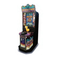
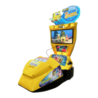
3 Check connection of motor connector , Check assembly status of motor ( P2,P3 )
4
Check the dc voltage ( MAIN PCB / CN19 )
: PIN 1 : Over 11V , PIN 3 : Below 0.5V , PIN 6 : GND ,
PIN 2 : Operation state over 4.5V / Non-operation state below 0.5V
5 Replace MOTOR
6 Replace MAIN PCB
▶SOLUTION -PUSHER SENSOR ERROR [E.41]
1 HOW TO TEST TEST MODE → PUSHER MOTOR TEST→ SELECT BUTTON →SHOOTING button
Sensor operation status : Detected Sensor : " _ " / Non-Detected sensor : " 0 "
1 Check if tokens, cards, balls, side token are jamming the pusher plate ( P1 )
2 Check connection of sensor connector , Check assembly status of sensor (P4 )
3 Check the dc voltage ( SENSOR PCB )
: PIN 1 : over 4.5V , PIN 2 : below 0.5V , PIN 4 : GND ,
PIN 3 : Detected Sensor over 4.5V / Non-detected sensor below 0.5V
Check the dc voltage ( MAIN PCB / CN19 )
: PIN 7 : Over 4.5V , PIN 8 : Below 0.5V , PIN 10 : GND
6 Replace MAIN PCB