Do you have a question about the Andco Eagle and is the answer not in the manual?
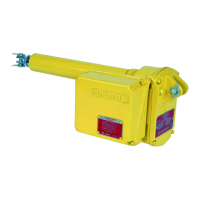
Details the Andco Eagle Linear Actuator's self-contained electro-mechanical design for easy installation and reliable operation.
Highlights high-starting torque motor, non-rotating rod, non-back driving screw, and all-metal gearing for robust performance.
Ensures actuators are stored in a clean, dry environment with covers and plugs secured to prevent damage.
Advises against lifting by the limit switch compartment and to follow safety guidelines during movement.
Suggests mounting with extension rod up or motor on top to ensure seal integrity, avoiding face-down positions.
Covers using body tube adapter for flange/trunnion mounting and clevis mounting via the extension rod.
Covers PPE, burn hazards, moving parts, voltage, conductor ratings, and lifting hazards during installation.
Details preventing side loading, protecting the extension rod, face/trunnion, clevis mounting, and applying lubricant.
Explains length adjustment, securing components, electrical code compliance, and proper conduit routing.
Recommends conduit seals and proper cover installation for dust-ignition proof enclosures to prevent moisture damage.
Details connecting the actuator enclosure grounding lug with a minimum #10 AWG wire to a suitable system.
Emphasizes disconnecting all electrical power before any adjustments or cover removal due to multiple live circuits.
Provides step-by-step instructions for setting extend and retract limit switches by rotating the motor shaft and engaging cams.
Warns about moving parts, hazardous voltage, and hot surfaces, stressing power disconnection before disassembly.
Guides on removing the limit switch compartment cover and disconnecting leads before removing the assembly.
Details disconnecting motor leads, removing retaining hardware, and carefully extracting the motor from the housing.
Explains loosening jam nut, unthreading clevis, and unthreading the body tube from the actuator housing.
Outlines removing intermediate gear, key, spacer, installing flex nut, and removing the drive screw/extension rod assembly.
Describes clamping the drive nut, using a spanner wrench to unthread the rod, and removing the bearing assembly and acme nut.
Reverses disassembly steps, detailing thread cleaning, Loctite use, flex nut replacement, and lubrication.
Details HIPOT testing, voltage settings, duration, and acceptable leakage current as per specified tables.
Verifies continuity between the actuator's ground lug and the main grounding system for safety.
Involves energizing the actuator and operating it through its entire range of motion to confirm functionality.
Explains actuators are factory-lubricated for life, but provides re-lubrication steps after disassembly with specified lubricants.
Provides checks for common problems: rod not moving, single-direction actuation, noise, or high motor current.
Describes the optional potentiometer for linear output signals and its adjustment procedure for stroke feedback.
Presents detailed dimensional data for the Eagle actuator, covering mounting configurations and key measurements.
Illustrates the internal components of the Eagle actuator with numbered callouts for easy part identification.
Provides a detailed list of all actuator components with corresponding item numbers for reference and ordering.
Lists essential spare parts, including drive nut, limit switches, motor, and gasket/seal kits for maintenance.
Illustrates the field wiring and actuator wiring connections for a single-phase Eagle actuator.
Covers limit switch data, optional components, grounding, heater wiring, and HIPOT testing for single-phase units.
Provides the wiring diagram for a three-phase Eagle actuator, detailing field and actuator wiring connections.
Includes limit switch data, optional components, grounding, heater wiring, and HIPOT testing for three-phase units.
Details operating temperature, humidity, and electrical ratings for Canadian and US applications.
Specifies motor insulation, design, stroke lengths, and speed/force capabilities at different velocities.
Lists certifications, mounting types, and available control/position card options.
Provides contact details for GE Oil & Gas, including address, phone numbers, email, and website for support.
| Brand | Andco |
|---|---|
| Model | Eagle |
| Category | Controller |
| Language | English |