REQUIRED COMPONENTS
• 18-22 gauge wire (field supplied), 4 wires required, run new cable as needed.
• (2) #8 x 1-1/2" mounting screws (supplied)
• (2) Anchors (supplied)
1. Level the back plate on the wall and mark the mounting holes and wire access location on the
wall.
2. Drill two 3/16" mounting holes and a 3/4" wire access hole. See FIGURE 3.
3. Install the drywall anchors flush with the wall surface. Note: Mounting holes on the back plate
are designed to fit on a horizontal J-box.
4. Run a 4-wire cable from the dehumidifier to the wall mount location and through the square
hole in the back plate.
5. Secure the back plate to the wall using the two #8 x 1-1/2" screws.
CONTROL
PANEL COVER
CONTROL
WIRING ACCESS
COVER
FILTER ACCESS DOOR
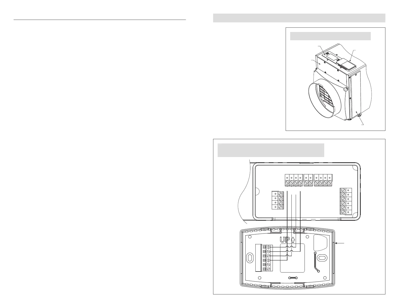
FIGURE 4 – WIRING ACCESS COVER LOCATION
90-1884
+ - A B ODT
SensorRemote
Gh Rf Cf Gs YW
HVAC EQUIP.
CONTROL
DH
DH
R/+
C/-
B
A
FIGURE 5 – MODEL A77 WIRING WITH DEHUMIDIFIER MODELS
A70, A95, A95F, A130, A130F, A210V1, A320V1 AND A320V3
90-2490
WIRING A77 WITH DEHUMIDIFIER MODELS A70, A95, A95F, A130, A130F, A210V1 AND A320V1
1. Disconnect power to the
dehumidifier and HVAC system.
2. Remove the wiring access
cover next to the control on the
dehumidifier. See FIGURE 4.
3. Wire the Model A77 to the
dehumidifier as shown in
FIGURE 5.
4. Ensure the NO/NC switch on the
dehumidifier control is set to NO.
See FIGURE 5.
76