9
PRODUCT MANUAL
68/72ST Above Deck Compact Motor
™
STEP 3
Prepare and dry-t the motor unit
3.1 Slide the stainless steel cover upward to remove it from the
motor unit (refer to the exploded diagram at the beginning of this
manual).
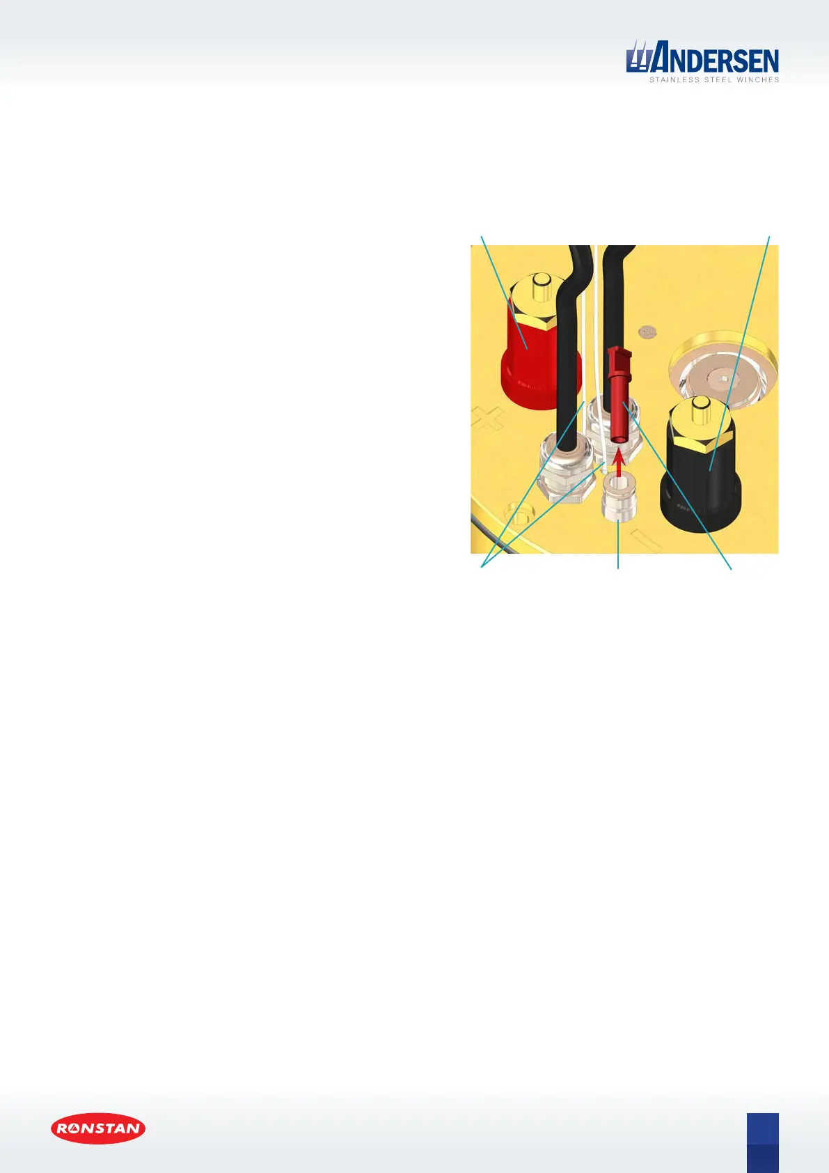
3.2 Fit the terminal extensions [A16] to the motor terminals,
ensuring that the RED extension is tted to the RED POSITIVE (+)
motor terminal, and the BLACK extension is tted to the BLACK
NEGATIVE (–) motor terminal.
3.3 Remove the plastic plug from the drain port tting and push the
drain tube [A14] into the tting until it stops. Lead the drain tube
below deck to a low point in the boat where it can drain to the
bilge, then cut o any excess length. At most there should only
ever be a drop or two of water from condensation that will pass
through the tube.
3.4 Place the motor in position on deck. The two wires for the
thermal sensor can be passed through the 25mm hole together
with one of the push button control cables. The other push
button control cable is passed through the 20mm hole. Ensure
that deck cut-outs and fastener holes align properly and there is
adequate clearance for a good t and assembly.
Thermal Sensor wires
and Control Cable for
Push Button
RED terminal extension
tted to RED POSITIVE (+)
motor terminal
BLACK terminal extension
tted to BLACK NEGATIVE ( – )
motor terminal
Plastic plug
removed from
drain port
Drain
port
 Loading...