INSTALLATION
MOUNTING ON ELECTRIC BOX
MOUNTING FRONT COVER
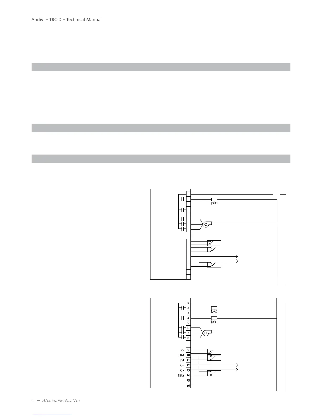
WIRING EXAMPLE
1. Separate the back plate from the controller by loosening the cover screw.
2. Align the mounting holes on the screw holes of the electric box. Suitable is a 3-module electric box 3M, for example Gewiss
GW24203, GW24207; TEM Catez DM30, HM30. The electric box is mounted vertically.
3. Fix the back plate on the electric box by tightening the back plate screws. Suggested for use is Philips wider “truss head”
or “washer head” #6-32x 3/4”(20mm).
4. DO NOT let the bolt head rise above the wall of the mounting holes of the back plate. It might cause a short circuit of the
room controller.
1. Lock front cover on the back plate by tightening the cover screw underneath with screwdriver of Philips electronic instrument
type or similar.
All wires that come from electric box must be inserted above the retainers of respective terminal block before tightening the
captive screws.
N L
1
2
3
4
5
6
7
8
9
10
11
12
13
14
15
16
ESI2
ESI
C+
C -
RS
COM
I.
II.
III.
Cooling/Heating valve
Economy mode input (ECON)
Remote sensor (RS)
Protect mode input (PROT)
Modbus
Fan