C139604000.fm
- 13 -
)4
'"
$%
&2
%3
%NGLISH
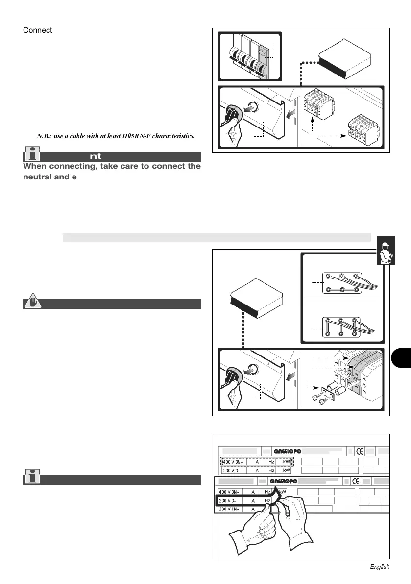
Connect the appliance to the mains electricity sup-
ply as follows.
1 - If not already present, install a circuit-breaker
(A) with overload cutout and differential safety
breaker close to the appliance.
2 - Remove the control panel (B).
3 - Connect the circuit-breaker (A) to the terminal
board (C) of the appliance as shown in the dia-
gram and in the electrical system diagram at the
back of the manual.
1%XVHDFDEOHZLWKDWOHDVW+51)FKDUDFWHULVWLFV
Important
When connecting, take care to connect the
neutral and earth lines.
4 - Replace the control panel (B) on completion of
the operation.
The appliance is supplied at an operating voltage
400V/3N (indicated on the sticker applied to the da-
taplate); conversion to 230V/3 can be carried out as
described below.
Caution - warning
Before doing any work, cut off the mains elec-
tricity supply.
1 - Remove the control panel (A).
2 - Fit the jumper (B) to make the electrical connec-
tion of the terminals (C) and (D).
3 - Change the connections of the terminal
board (E) as shown in the diagram.
4 - Replace the control panel (A).
5 - Remove the test voltage indicator sticker from
the dataplate and apply the new one to identify
the voltage being used.
Important
On completion of the operation make sure
that there are no malfunctions.
CONVERSION OF ELECTRICITY SUPPLY
A
B
IDM-39604002300.tif
C
IDM-39604002200.tif
A
C
D
B
E
E
400V/3N
230V/3
IDM-39603620000.tif
 Loading...