EN 7675 EN
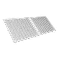
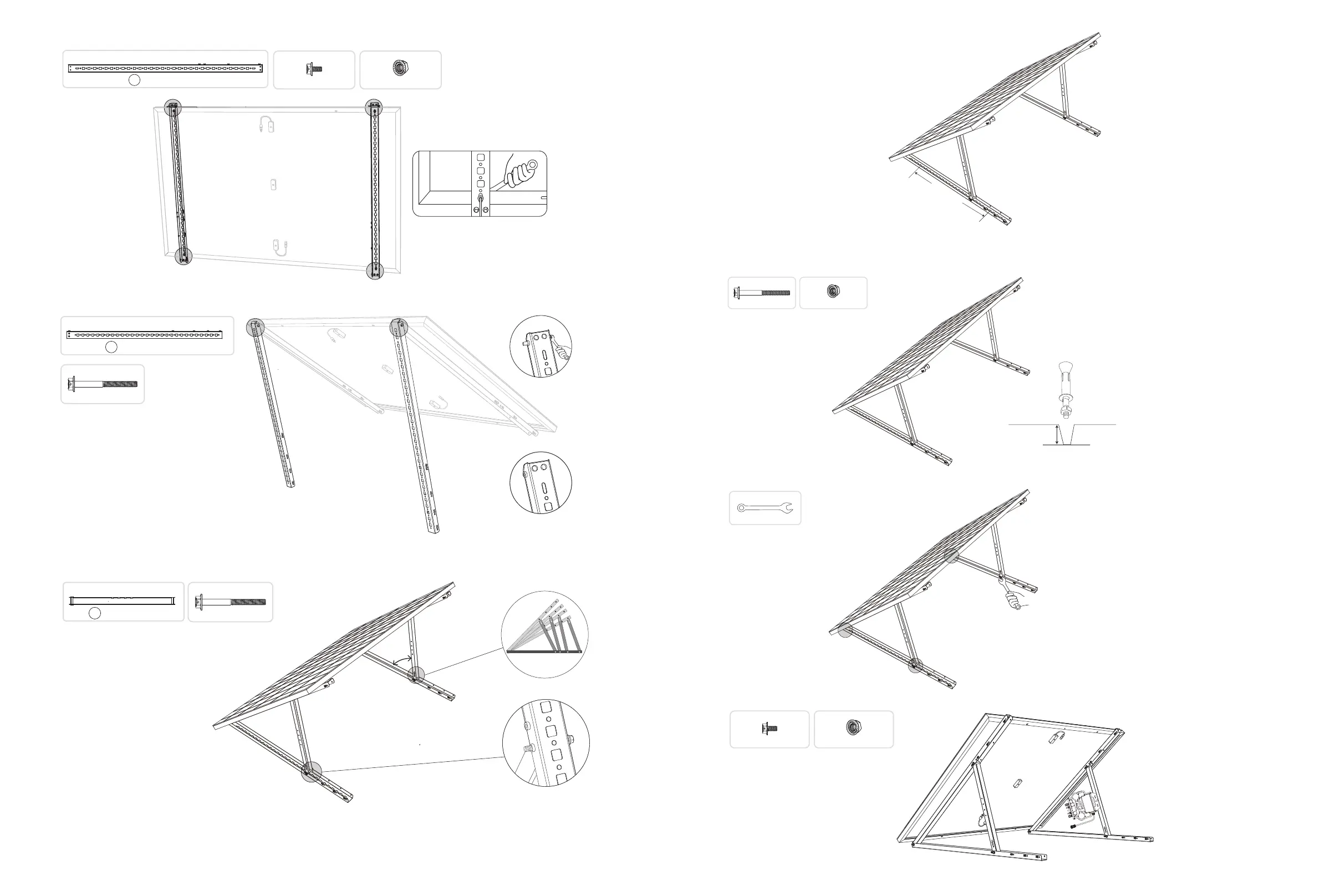
2. Mount the solar panel support beams on the solar panel.
I x4
M6×12 Hexagon Flange Bolt
J x4
A x2
Solar Panel Support Beam
mm
1200
M6 Flange Nut
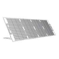
3. Install the vertical support scaoldings and solar panel support beams without tightening the screws.
M6×65 Hexagon Flange Bolt
H x2
B x2
Vertical Support Scaolding
mm
110 0
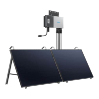
4. Mount the lower support beams and adjust the angle for maximum sunlight exposure.
Note: Make sure that both ends of the lower support beams are aligned with the same number.
°~°
45
40
35
30
45
40
35
30
A
C
B
45
40
35
30
45
40
35
30
45 40 35 30
M6×65 Hexagon Flange Bolt
H x4
C x2
mm
618
Lower Support Beam
5. Align the solar panel with the holes on the vertical support scaoldings to mark four mounting points. Mounting points on the
same vertical support scaolding should be 800mm (31.4in) apart.
6. Remove the solar panel, mark the mounting points, and drill the holes 63mm (2.4in) deep with an electric drill. Then, secure
the scaolding with nuts.
Note: The vertical scaolding should be secured with anchors to prevent them from falling.
M6×65 Hexagon Flange Bolt
H x2
J x2
M6 Flange Nut
7. Tighten all the screws with 5N.m torque.
5N.m
N x1
Hexagon Wrench
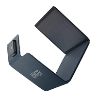
8. Install the microinverter to the lower support beams.
I x2
M6×12 Hexagon Flange Bolt
J x2
M6 Flange Nut
 Loading...