ASC+ System Auto Split Charge & Engine Start Protect
User Guide and Installation Instructions
Document No 13362 Issue 04 Page 6 of 21
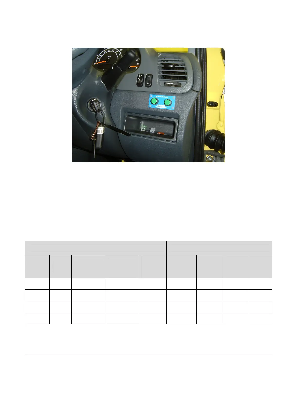
Figure 1: Typical switch mounting positioning:
Control cables
The system consists of the following control cables:-
• 1 off, 6 way control to user panel loom
• 2 off, 4 way control to contactor looms
Contactor type & rating
The system consists of 2 off latching contactors; see Table 1 for rating
System operating values (nominal) Contactor contacts rating
System
No
DC
Voltage
Operating
Voltage
Range
System
current draw
*IQ mA
*State
change
Pulse
current
Continuous
Current
Peak
current
5 Sec
Max
Cranking
Current
Heavy
Load
3 Min
Max
90907 12V 8V-16V 28/8/1 1.6A 125A 800A 600A 280A
90908 12V 8V-16V 28/8/1 2.6A 250A 1500A 1200A 650A
90917 24V 18V-32V 28/8/1 0.8A 125A 800A 600A 280A
90918 24V 18V-32V 28/8/1 1.5A 250A 1500A 1200A 650A
*IQ: A/B/C A = Switch LEDs + Controller, B = Controller Normal, C = Controller Sleep Mode
(controller enters sleep mode 24 hours after both contactors off)
*State change: Pulse current at nominal voltage during the contactor change of state (Pulse length 100ms)
Table 1