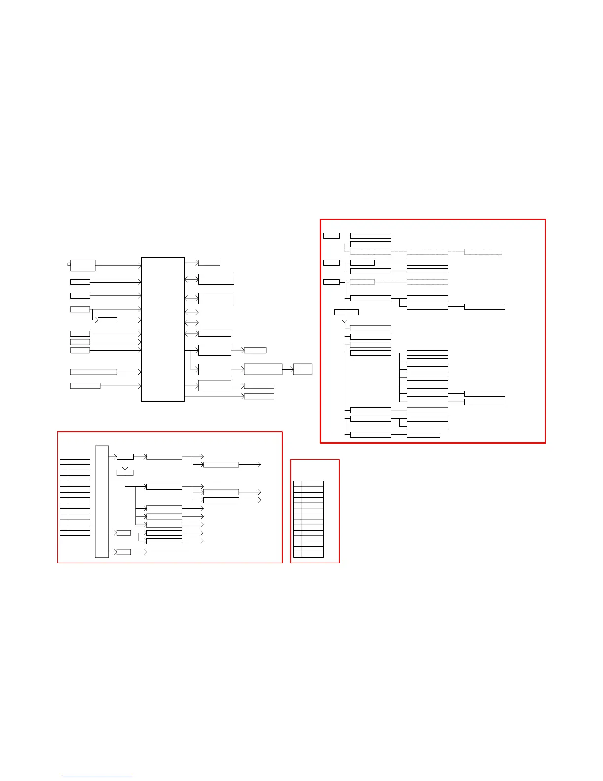
EasyManua.ls Logo

AOC LC42H163 User Manual

AOC LC42H163
88 pages
To Next Page IconTo Next Page
To Previous Page IconTo Previous Page
Page #43 background image
43
8. Block Diagram
GPIO
EJTAG
Earphone Amplifier
MAX9728AETC+
CAT24C64WI-GT3
SPEAKER
I2S
SPDIF Output
EarPhone
Output
Audio Amplifier
STA339BWTR
Audio DAC
PCM1754DBQR
R\L
Audio Lineout
Audio Driver
DRV602PW
IEC958
R\L
CVBS
VIDEO
YPbPr
YPbPr
For ZR39748BGCGU401 ZR39748BGCG
DDRII
W9751G6JB-18
FLASH ROM
MX25L3206EM2I-12G
Hsync, VsyncSN74LVC1G17
16V
NC
HDMI_1
HDMI_3
Under 26" TV
1
7
3
PWR_ON_STB
10
4
GND
16V
CVBS & YPbPr AUDIO-R\L
TMDS
13
11
2
5
Function
5.2V
VGA AUDIO-R\L
TMDS
5.2V
8
GND
BL_ON_OFF
HDMI_2
NC
Pin
6
BL_BRI_ADJ
TMDS
Reserved
GND
12
9
Power Board Input : +5VSB, P12V, P24V
Upward 32" TV
VGA
RGB
P12V
U710 G9141T11U
+5VSB
Max. 2A
Max. 0.6A
VCC1_1
3V3_STB
Max. 1A
Audio Amplifier
STB 15mA
U703 G9141T11U
Max. 1A
PLL3_3
1V1_STB
U704 G1084-33T43Uf
U707 G5692P11U
VCC5D VCC3_3
AO4449
PANEL LVDS Power
VCC1_8
AO4449
Max. 5A
U706 SC189ASKTRT
Max. 1.5A
U701 AZ1117D
Max. 2.5A
MSD_1V1
U705 G1117-33T63Uf
Max. 1.5A
Max. 0.6A
Power Board Input :
+5VSB, P16V
POWER
BOARD
U711 G9141T11U Max. 0.6A
AFE_1V1
Max. 5A
U709 G9084-50TU3U
5VT
U602 STA339BWTR For Audio Amplifier
P24V
5.2V
3
6
12
Function
12V
4
5.2V
GND
BL_ON_OFF
GND
8
GND
9
2 BL_BRI_ADJ
24V
13
24V
12V
Pin
5
11
10 PWR_ON_STB
PWR_OK
7
1
U708 AS7812ADTR-G1
5VT
For ZR39748BGCG
+5V SB
VCC1_1
U704 G1084-33T43Uf U401 ZR39748BGCG
For SPI Flas h
PANEL Inve r te r
U706 SC189ASKTRT
U406 CAT24C64WI-GT3
VCC1_8
U709 G9084-50TU3U
TU101 ENV56U04D8F
U402 W9751G6JB-18
Q702 AO4449P12V
For Audio Am p lifie r
Fo r EEPRO M
9V
Fo r TUNER+5V
For T UNER+5V
U401 ZR39748BGCG
Q702 AO4449
Q702 AO4449
U405 MX25L3206EM 2I-12G
3V3_STB
PANEL LVDS Pow er
For ZR39748BGCG
U701 AZ1117D
Fo r DDR II
For ZR39748BGCG
TU101 ENV56U04D8F
PANEL LVDS Pow er
VCC3_3
U602 STA339BWTR
5VT
P24V/16V
VCC5D
U401 ZR39748BGCG
Main Board Power System
U707 G5692P11U
P24V/16V
U709 G9084-50TU3U
For Audio Lineout DriverU603 DRV602PW
U710 G9141T11U For ZR39748BGCG
MSD_1V1
AFE_1V1
U711 G9141T11U
U401 ZR39748BGCG
For ZR39748BGCGU401 ZR39748BGCGU705 G1117-33T63Uf
PLL3_3
USB5V
For Audio Headphone Am plifier
5V_HP
For USB OC PU409 G5250M1T1U
U606 MAX9728AETC+
For Audio DAC (Headphone)U604 PCM 1754DBQR
Tuner
ENV56U04D8F
LCD PANEL
System Block Diagram
LVDS
ZR39748BGCG
VIF
U401 ZR39748BGCG
U401 ZR39748BGCG
1V1_STB
U703 G9141T11U For ZR39748BGCG uMCU
For ZR39748BGCG uM CU
Question and Answer IconNeed help?

Do you have a question about the AOC LC42H163 and is the answer not in the manual?

AOC LC42H163 Specifications

General IconGeneral
BrandAOC
ModelLC42H163
CategoryLCD TV
LanguageEnglish

Summary

Safety Notice

Important Safety Notice

Revision List

General Specifications

Operating Instructions

Remote Control Functions

Explains the function of each button on the remote control.

Menu Navigation and Settings

Instructions for navigating and using the TV's on-screen menus and various settings.

Channel Search and Tuning

How to tune, search, and manage TV channels using the OSD menu.

Channel Selection

Procedures for changing TV channels via remote or TV controls.

Audio and Volume Controls

Controls for adjusting TV volume, mute, and sound modes.

Video Settings Configuration

How to adjust picture settings like brightness, contrast, and color.

Audio Settings Configuration

How to adjust audio settings like sound mode, bass, treble, and balance.

PC Mode Settings

Settings for connecting and configuring the TV as a PC monitor.

System and Time Settings

Settings for menu language, time, and basic system configurations.

Parental Controls Setup

Guidance on setting up and using the parental control (V-chip) features.

Connecting External Devices

Instructions for connecting various external audio and video sources to the TV.

Front Panel Controls

Overview of the TV's physical buttons and their functions.

Input/Output Specifications

RGB Signal Input Pin Assignments

Pin configuration details for the RGB (VGA) signal input.

HDMI Digital Connector Pin Assignments

Pinout details for the HDMI digital connector.

Compatible Signal Modes

Tables listing compatible PC and Video signal modes and frequencies.

Mechanical Instructions

Repair Flow Charts

No Power Troubleshooting

Flowchart to diagnose and resolve issues related to the TV not receiving power.

No Power On Troubleshooting

Flowchart to diagnose and resolve issues when the TV does not turn on.

Abnormal Image Troubleshooting

Flowchart for diagnosing and fixing problems with abnormal or distorted picture display.

No Image Troubleshooting

Flowchart to troubleshoot scenarios where the TV displays no image.

Sound Problems Troubleshooting

Flowchart for diagnosing and resolving issues with no or abnormal sound output.

Remote Control Malfunction

Troubleshooting steps for a non-functional or poorly functioning remote control.

OSD Instability Troubleshooting

Diagnosing and fixing issues with an unstable or unresponsive On-Screen Display (OSD).

PCB Layouts

Main Board Layout

Detailed layout diagram of the TV's main printed circuit board (PCB).

Power Board Layout

Detailed layout diagram of the TV's power supply printed circuit board (PCB).

Key Board Layout

Layout diagram of the TV's key input board.

IR Board Layout

Layout diagram of the TV's infrared (IR) receiver board.

Adjustments

ADC Adjustment

Steps for performing Analog-to-Digital Converter (ADC) adjustment for white balance.

Firmware Upgrade

Instructions on how to update the TV's firmware using a USB drive.

Block Diagrams

Schematic Diagrams

Main Board Schematic

Electronic schematic diagram for the TV's main board.

Power Board Schematic

Electronic schematic diagram for the TV's power board.

Key Board Schematic

Electronic schematic diagram for the key board.

IR Board Schematic

Electronic schematic diagram for the IR board.

Exploded View

BOM List

Related product manuals