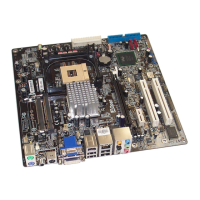
Connecting IDE and Floppy Cable
Be careful of the pin1 orientation. Wrong orientation may cause system damage.
Pin1 of cable is normally marked with red color.
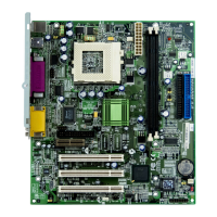
ttach the power LED, keylock, speaker, and reset
switch connectors to the corresponding pins. Locate
the power switch cable from your ATX housing. It is
2-pin female connector from the housing front panel.
Plug this connector to the soft-power switch connecto
marked SPWR.
Connecting Front Panel Cable
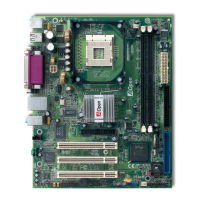
Connecting ATX Power Cable
The ATX power supply uses 20-pin connector shown
below. Make sure you plug in the right direction.
+12V
-12V
+5V
5VSB
+3.3V
+5V
PSON
-5V
GND
+5V
PWOK
GND
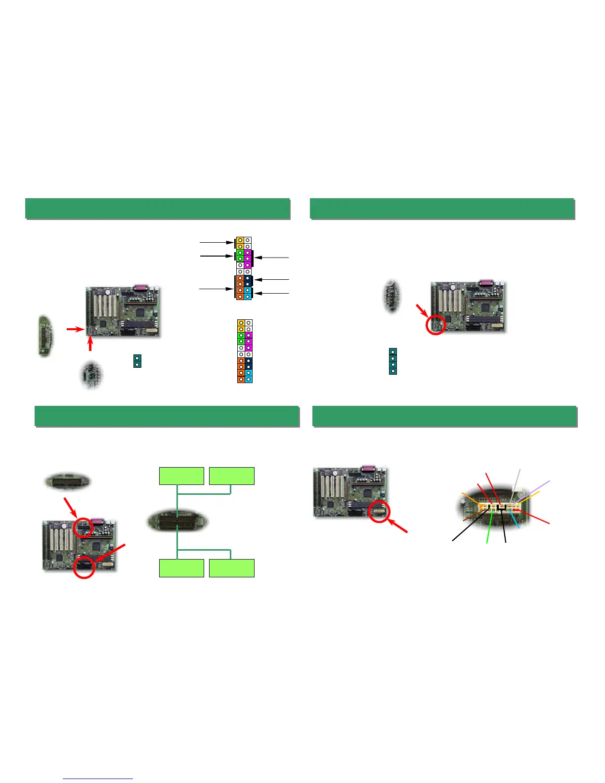
Hard Disk LED
The HDD LED connector is designed for different type of housing, actually only two
pins are needed for the LED. If your housing has 4-pin connector, simply plug it in. If
you have only 2-pin connector, please connect to pin 1-2 or pin 3-4 according to the
polarity.
1
Speaker
Sleep LED
Keylock
+
+
+
+
+
Power LED
Reset
1
+5V
GND
POWER LED
GND
GND
NC
GND
SLEEP SWITCH
RESET
GND
GND
KEYLOC
+
Sleep SW
Pin 1
Pin 1
IDE1 (Primary)
IDE2 (Secondary)
Slave (4th)
Master (1st)Slave (2nd)
Master (3rd)
FDC
1
2
SPWR
HDD LED
GND
GND
HDD LED
1
2
3
4
 Loading...