2/ 6
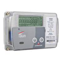
1. Fiber glass reinforced polycarbonate housing.
2. Marker triangles, for wM-Bus push signal, Terminal cover opening (CZO) and
magnetic influence indicator (RPM), etc.
3. Multifunction LCD display (all measurement data displayed on the display and an
explanation thereof according to the tables below).
4. Optical interface for reading measurement data, EN 62056-21 (IEC-1107 readout
only/ DLMS-COSEM readout and parameterization).
5. Nameplate: nominal parameters of the meter, accuracy class, markings defining the
mechanical and electrical environment for the meter to be installed at.
6. Display content samples (display test and measurement data sample explanation to
the end user).
7. Wiring diagrams for main and RS485 communication terminals.
8. Name and address of manufacturer.
9. Pulse transmitter red LEDs for validation and accuracy verification.
10. Serial number and barcode.
11. Push buttons (for faster scrolling of display content back and forth with arrows).
12. Push button with sealable lid (for service menu).
13. Replaceable battery cover.
14. Cage clamp terminal block.
Two freely accessible buttons on the front panel of the meter are dedicated for manual scrolling
of measurement data on the LCD which has been programmed during the factory
parameterization. The push button with sealable lid can be used to clear the indicators of
terminal cover opening and magnetic influence tamper markers, as well as to enter the service
menu. It is highly recommended to protect this third pushbutton by closing and sealing its lid
during the installation of the meter.
Sealable push button:
After opening the lid and pressing the button once,
the meter enters the so-called service menu. Within
this, we can move from right to left with the two
buttons above.
 Loading...