Do you have a question about the Apator FAUN D204MB and is the answer not in the manual?
Steps for mounting the calculator unit onto a wall using a mounting base and screws.
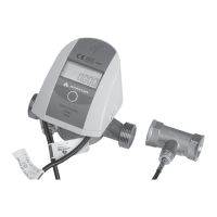
Procedure for attaching the calculator to an ultrasonic flow sensor's mounting slot.
Guide for connecting Pt500 temperature sensors (2-wire and 4-wire) to the calculator.
Instructions for connecting the main flow sensor via a 3-terminal connector.
Wiring diagram for connecting the Sharky 473 ultrasonic flow sensor.
Wiring diagram for connecting the Ultraflow ultrasonic flow sensor.
Procedure for installing the M-Bus communication module (code 001).
Procedure for installing the RS 232 communication module (code 003).
Procedure for installing the RS 485 communication module (code 003).
Procedure for installing the LonWorks communication module (code 002).
Procedure for installing the Wireless M-Bus communication module (code 004).
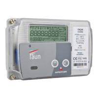
Explanation of various symbols displayed on the calculator's LCD screen.
Procedure for editing numeric values using the calculator's buttons.
Steps for configuring the date and time settings of the calculator.
Details of displayed values for energy, volume, mass, and temperature.
Details of displayed average, maximum, and minimum values.
Details of displayed meter, I/O, and register information.
Details of displayed tariff and archive information.
Details of displayed archive types, including flow and temperature data.
Details of displayed configuration confirmation and customer information.
| Accuracy Class | Class B |
|---|---|
| Rated Voltage (Un) | 230 V |
| Rated Current (In) | 5 A |
| Frequency | 50 Hz |
| Impulse Constant | 1000 imp/kWh |
| Display | LCD |
| Mounting | DIN rail |
| Voltage Range | 160-276 V |
| Communication Interface | M-Bus |
| Operating Temperature | -25°C to +55°C |