EN
Installation of additional modules
The calculator allows you to install up to two independ-
ent additional modules:
– M-Bus
– RS232
– RS485
– impulse outputs (2x OB, OC or OD class output)
– impulse inputs and outputs (2x OB, OC or OD class
output and 2x IB or IC class input)
– analogue outputs (2x 4-20 mA or 0-10 V output)
– LonWorks
– RF module for IMR telemetry systems (AIUT)
– Wireless M-Bus RF module.
Fig. 21.
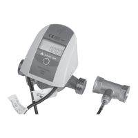
Fig. 21 shows the place and method of additional mod-
ule installation. Modules can be installed in any con-
nector except for RF modules, which can only be fitted
in the connector marked with number 1 (Fig. 9).
Installation of the M-Bus module
(module code: 001)
M-Bus module is powered from the M-Bus network and gal-
vanically isolated from the calculator using optical isolation.
The module supports primary, secondary and extended
secondary addressing. The M-Bus signals are connected
through the inputs marked with numbers 24, 25 (Fig. 22).
Installation of the RS 232 module
(module code: 003)
The RS 232 module requires an external power source. It
is galvanically isolated from the calculator using optical
isolation. The module can be powered by AC or DC volt-
age. The power source is connected through terminals
no. 97, 98, the polarity of the connected power supply
is arbitrary. The communication cables are connected
through the following terminals: 64 – signal ground, 63
– TxD module output, 64 – RxD module input (Fig. 23).
Installation of the RS 485 module
(module code: 003)
The RS 485 module requires an external power source.
The module has no galvanic isolation between the
power supply and the RS485 bus, and special care
should be taken when connecting various devices to
the bus. It is galvanically isolated from the
calculator using optical isolation. The module can be
powered by AC or DC volt-age. The power source is
connected through terminals no. 97, 98, the
polarity of the connected power supply is arbitrary.
The communication cables are connected through
the following terminals: 86 – signal ground, 85 – A+
input/output (non-inverting), 85 – B- input/output
(inverting) (Fig. 24).
Installation of the LonWorks module
(module code: 002)
The LonWorks module (Fig. 25) requires
an external power source. The module can be
supplied with direct current at a voltage range
of 9-24 V. Power source is connected by means
of a pair of terminals located in the upper right
part of the module designated as B. The positive
terminal is marked as Vcc, whereas the negative
pole – as GDN. Communication cables are
connected by means of a pair of terminals located
in the upper left part of the module designated as A
– the polarity is arbitrary.
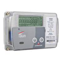
Installation of the Wireless M-Bus module
(module code: 004)
The Wireless M-Bus module (Fig. 26) is battery-powered
and has its own antenna, so for the purpose of proper
operation of the module, just put it in the appropriate
connector.
NOTE! Wireless M-Bus modules can be mounted only
in the connector marked with number 1 (Fig. 9).
Fig. 22. Fig. 23.
WYK.
MBUS
24 25
WYK.
RS232
Vin
8 ...30V
6 ...30V
97 9864 63 62
GND TxD RxD
Fig. 24. Fig. 25.
WYK.
RS485
Vin
8 ...30V
6 ...30V
97 9886 85 84
GND A+ B-
A B
GDN Vcc
Fig. 26. Fig. 27.
2
1
6
5
2
1
6
5
34 35
SW1
+3 1 -3 2
Connection
of many devices
on the RS-485 bus
RS485
FAUN
DEV2
A
B
GND
DEVn
A B GND
A
B
GND
A
B
GND
 Loading...