EN
Electrical connections
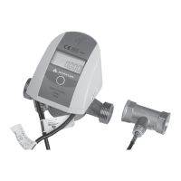
To make electrical connections, remove the C cover of
the calculator (Fig. 5). The removal method is described
in the section „Installation of the calculator.”
Connecting the temperature sensors
Temperature measurement can be performed using
the Pt500 sensors, both 2- and 4-wire. De-pending on
the number of temperature sensor connec-tion wires,
the calculator connection strips are available in two
versions (Fig. 9):
Fig. 9.
– calculator with a strip for 2-wire temperature sensor,
a strip for the connection of the main flow sensor
and a strip for the connection of 4 additional devices
(Fig. 10),
Fig. 10.
– calculator with a strip for 4-wire temperature sensor,
a strip for the connection of the main flow sensor
and a strip for the connection of 4 additional devices
(Fig. 11).
Fig. 11.
When measuring with 2-wire sensors (Fig. 10), the T1
sensor (power supply temperature) must be connected
to the connector marked with numbers 5, 6, whereas
the T2 sensor (return temperature) – to connector no.
7, 8. When measuring with 4-wire sensors (Fig. 11), the
T1
sensor must be connected to the connector marked
with numbers 5, 6 and 1, 2, whereas the T2 sensor – to
connector no. 7, 8 and 3, 4.
The connection of the main flow sensor is made through
a 3-terminal connector, marked with numbers:
9 – power supply output for flow sensor (from the main
power source),
10 – signal input for the flow sensor,
11 – signal reference input for the flow sensor.
What is more, there is a possibility of connecting the
flow sensor communication cable to the signal input –
the fourth additional input (53) (only if it is configured as
a input of digital communication with the flow sensor).
Fig. 12.
Fig. 12 shows the method of connecting flow sensors
with open collector output for the sensor requiring
power supply from the calculator (1), open collector
output (2) and normally open contact output (3).
Connecting the flow sencor with NC transmitter
- connection polarity arbitrary (Fig. 13)
Fig. 13.
BROWN
WHITE
Connecting Sharky 473 ultrasonic flow sensor (Fig. 14)
Fig. 14.
BROWN
WHITE
BLUE
YELLOW
Connecting Ultraflow ultrasonic flow sensor (Fig. 15)
Fig. 15.
RED
YELLOW
BLUE
Note: in the case of ultrasonic flow sensors with a 4-wire
connection (eg Sharky 473) the fourth wire (yellow) can
be connected only if input I4 is configured as a digital
communication with the flow sensor. Otherwise, do not
connect this cable. Incorrect connection may result in
premature battery wear.
 Loading...