EN
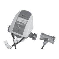
The additional flow sensor may be used to detect leaks
of the systems operating in the closed system. It should
be connected to the additional input 3. The sensor
should be connected with the 2 terminal connector
marked with the following numbers:
54 - signal input for the additional flow sensor,
50 - additional flow sensor signal reference output.
Moreover, you can also connect the sensor communica-
tions and power supply input:
9 - power supply output for the flow sensor (from the
main power supply source),
55 - signal input to communicate with the additional
flow sensor (additional input 2) (only if it is configured
as a input of digital communication with the flow
sensor).
Please refer to the diagram below (fig. 16) to connect
the additional flow sensor with the open collector
output for the sensor with the required power supplied
from the calculator (1), open collector output(2) and the
normally closed contact output (3)
Fig. 16.
Connecting external power supply
The calculator can be powered from 230VAC or 24VAC
power adapter, as well as using AA batteries, two AA
or C batteries mounted on a separate plate or D bat-
tery mounted directly in the base. Opening the cover
provides direct access to the main battery or power
adapter (Fig. 19). If you are replacing the D battery on
your own, pay attention to how it is mounted in the cas-
ing, the positive pole should be facing the upper edge
of the casing. Each battery or power adapter has cables
to be connected to the calculator. Main power supply
must be connected on the terminal block (Fig. 9) to the
connector marked with numbers: 60 – positive pole,
61– negative pole.
In case of calculator equipped with power supply: the
power adapter should be connected to the ~230 V
power supply and to the terminals marked with num-
bers 27 and 28 (Fig. 18); for the 24 V power adapter the
~24 V power should be supplied to terminals marked
with numbers 97, 98 (Fig. 19).
The power adapter has two sets of terminals marked
with numbers 95 and 96, allowing for the supply of
power to interchangeable communication modules
(terminals on modules marked with
numbers 97 and
98). The electrical connection of power adapter should
be performed by a properly licensed person.
Fig. 17.
Fig. 18. Fig. 19.
97
24VA C
98
Connecting additional input signals
Each version of the terminal block has 4 additional
inputs. Each of the inputs marked I1 (terminal no. 56
and 50), I2 (terminal no. 55 and 50), I3 (terminal no. 54
and 50), I4 (terminal no. 53 and 50) can operate as an
impulse input, the I3 input can additionally serve as an
alarm input or additional flow sensor conection, and the
I2 and I4 inputs can be used for digital communication
with the flow sensor.
Each input has two terminals, marked as follows:
– signal input (terminal no. 56, 55, 54, 53)
– reference input for additional input, each input has
a separate terminal for reference signal connection
(term
inal no. 50).
Fig. 20.
Fig. 20 shows the signal connection method for a sam-
ple additional input, for a device with output type: open
collector (1), normally open contact (2).
Note: in the case of ultrasonic flow sensors with a 4-wire
connection (eg Sharky 473) the fourth wire (yellow) can
be connected only if input I2 is configured as a digital
communication with the flow sensor. Otherwise, do not
connect this cable. Incorrect connection may result in
premature battery wear.
 Loading...