Do you have a question about the APE 100 and is the answer not in the manual?
General information about the manual's scope and purpose.
Instructions on how to effectively use the manual.
List of abbreviations used throughout the manual.
List of precautions for personal and equipment safety.
Standard warranty terms and conditions for APE products.
Overview of the APE Model 100 Vibro and Model 350 Power Unit features.
Detailed specifications for Model 100 Vibro and Model 350 Power Unit.
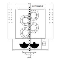
Description of the Model 100 Vibro, its function, and major parts.
Details on the suppressor housing, its location, and function.
Description of the vibrator gearbox, its design, and operation.
Explanation of the sprocket drive's function and connection.
Lists and illustrates optional attachments for APE Vibratory Hammers.
Description of the Model 350 Power Unit and its connection to the Model 100 Vibro.
Identifies components of the Model 100 Vibratory gearbox with a diagram.
Lists major components and part numbers for the APE 100.
Identifies major components of the Model 350 Power Unit skid with a diagram.
Details the APE Quick Disconnect Couplings and their design features.
Identifies the tool set provided with the Model 350 Power Unit for the Model 100 Vibro.
| Output Power | 100W |
|---|---|
| Input Voltage | 100-240VAC |
| Output Voltage | 12VDC |
| Efficiency | 85% |
| Protection Features | Over Voltage Protection, Over Current Protection, Short Circuit Protection |