24
APEC RO SYSTEM FLOW DIAGRAM
5th Stage Filter
PRODUCT
WATER
TANK
FAUCET
MAIN
WATER
SUPPLY
FEED WATER
NEEDLE VALVE
MAIN WATER SUPPLY
SHUT-OFF VALVE
CARBON
PRE-FILTER
CARBON
PRE-FILTER
2nd Stage
3rd Stage
SEDIMENT
PRE-FILTER
1st Stage
ESO
TSO
PUMP
CHECK VALVE
(BUILT IN)
4th Stage
R.O. MEMBRANE
PRODUCT WATER
FLOW RESTRICTOR
(BUILT IN)
INLET
TEE
FITTING
TANK
BALL
VALVE
TO WASTE WATER
DRAIN
BRINE
Part I: RO BASICS
This section provides basic concepts on how an RO system works, how it performs in relation to your
house’s water condition. We hope this information helps keep your RO system running at top
performance for years to come.
1) Basic Terms
GPD = Gallons Per Day (flow rate)
PSI = Pounds per Square Inch (pressure)
TDS = Total Dissolved Solids (contaminants)
PPM = Parts Per Million (unit used to measure TDS level)
TDS Meter = A digital meter for measuring the TDS level in the water
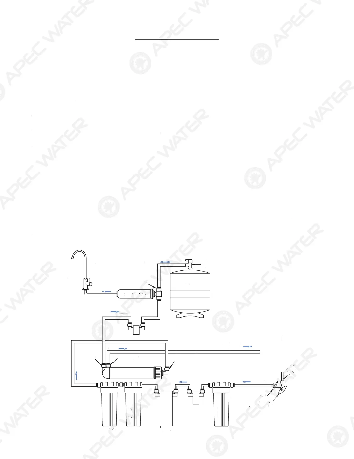
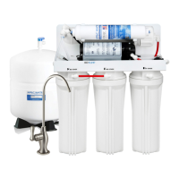
2) Flow Diagram for 5-Stage RO System:
Fig.15 below shows how water flows through the RO system from Feed point to Output point.
Input water starts from Main Water Supply, going through stages 1, 2, 3 pre-filters, then enters the
stage-4 membrane. Product (filtered) water from the membrane feeds the storage tank; the
“discharge water” from the membrane drains out through the drain line. Product water from the
tank passes through stage-5 filter filter before reaching the dispensing faucet.
Fig. 15
PEC RO SYSTEM FLOW DIAGRAM
th
ROD
E
EEDLE
CARB
RE-FIL
O
n
3r
e
-
1st
tage
S
T
HE
K
BUILT IN
th Stag
LOW RESTRI
TO
BUILT IN
NLET
T
TE
RAIN
P
rt I: R
BA
I
This section provides basic concepts on how an RO system works, how it per
orms in relation to you
house’s water condition. We hope this in
ormation helps keep your RO system running at top
r
ormance
or
ars to come.
Basic Terms
GPD = Gallons Per Day (
low rate
SI = Pounds
er S
are Inch
ressur
TDS = Total Dissolved Solids (contaminants
PM = Parts Per Million (unit used to measure TDS leve
TDS Meter = A digital meter
or measuring the TDS level in the wate
Flow Diagram
or 5-Stage RO System:
F
g.15
below shows how water
lows through the RO system
rom Feed point to Output point.
nput water starts
rom Main Water Supply, going through stages 1, 2, 3 pre-
ilters, then enters the
t
e-4 membrane. Product
iltere
water
rom the membrane
eeds the stora
tank; th
discharge water”
rom the membrane drains out throu
the drain line. Product water
rom th
tank passes through stage-5
ilter
ilter be
ore reaching the dispensing
aucet.
F
g. 1



 To Next Page