EasyManua.ls Logo

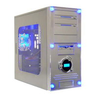
Apevia X-Dreamer II ATXB4KLW Series User Manual

Apevia X-Dreamer II ATXB4KLW Series
6 pages
To Next Page IconTo Next Page
Page #1 background imageLoading...
Page #1 background image
ATXB4KLW(X-Dreamer II) Series Installation Guide
1:Unscrew the thumb screws 2.Pull the side panel back then 3:Find the motherboard stand-offs
from side panel. pull out. from the enclosed screw box.
4:Put the motherboard stand-offs 5.Sit the motherboard on the 6.Find screws in the screw box.
on the motherboard tray. motherboard tray.
7.Screw in all the screws into the 8.Same as Step 7.
motherboard stand-offs
Question and Answer IconNeed help?

Do you have a question about the Apevia X-Dreamer II ATXB4KLW Series and is the answer not in the manual?

Apevia X-Dreamer II ATXB4KLW Series Specifications

General IconGeneral
BrandApevia
ModelX-Dreamer II ATXB4KLW Series
CategoryComputer Accessories
LanguageEnglish

Summary

Motherboard Installation

Prepare Case and Install Stand-offs

Unscrew side panel, find motherboard stand-offs, and place them on the motherboard tray.

Mount Motherboard

Sit the motherboard on the motherboard tray and screw it in place.

Front Panel and Drive Bay Preparation

Remove Front Panel

Unscrew side panels and front panel screws to detach the front panel from the case.

Install Optional Fans and Drives

Install case fans in the front or rear, and prepare the 5.25" drive bays.

Drive Installation and Front Panel Reassembly

Secure Drives

Secure 5.25" and 3.5" drives in their respective bays using screws.

Reassemble Front Panel and I/O

Snap the front panel back into place, screw it to the case, and install the I/O slot.

Connect Audio Cables

Route audio cables through the I/O slot to the outside of the back panel.

Internal Wiring and Component Connections

Connect Power Supply Cables

Connect 4-pin fan, 20-pin motherboard, and 4-pin P4 power connectors.

Connect Data and Front Panel Headers

Connect USB cables and front panel headers like HDD LED and Reset SW.

Additional Component Integration

Connect Power Switches and LEDs

Connect power switch, LED, and case speaker cables to the motherboard.

Install Special Features

Install LED lights and connect the LCD temperature readout sensor.

Final Setup and Finishing

Position Temperature Sensor and Install Feet

Place the temperature sensor and attach the case feet.

Related product manuals