2500+ Bus Compressor API
10.0 Power Switch & Rear Panel Connections
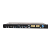
10.1 Power Switch
The power switch for the 2500+ is located on the right side of the front panel.
Power: Toggle to power the 2500+ ON and off
• Blue LED illuminates when powered ON
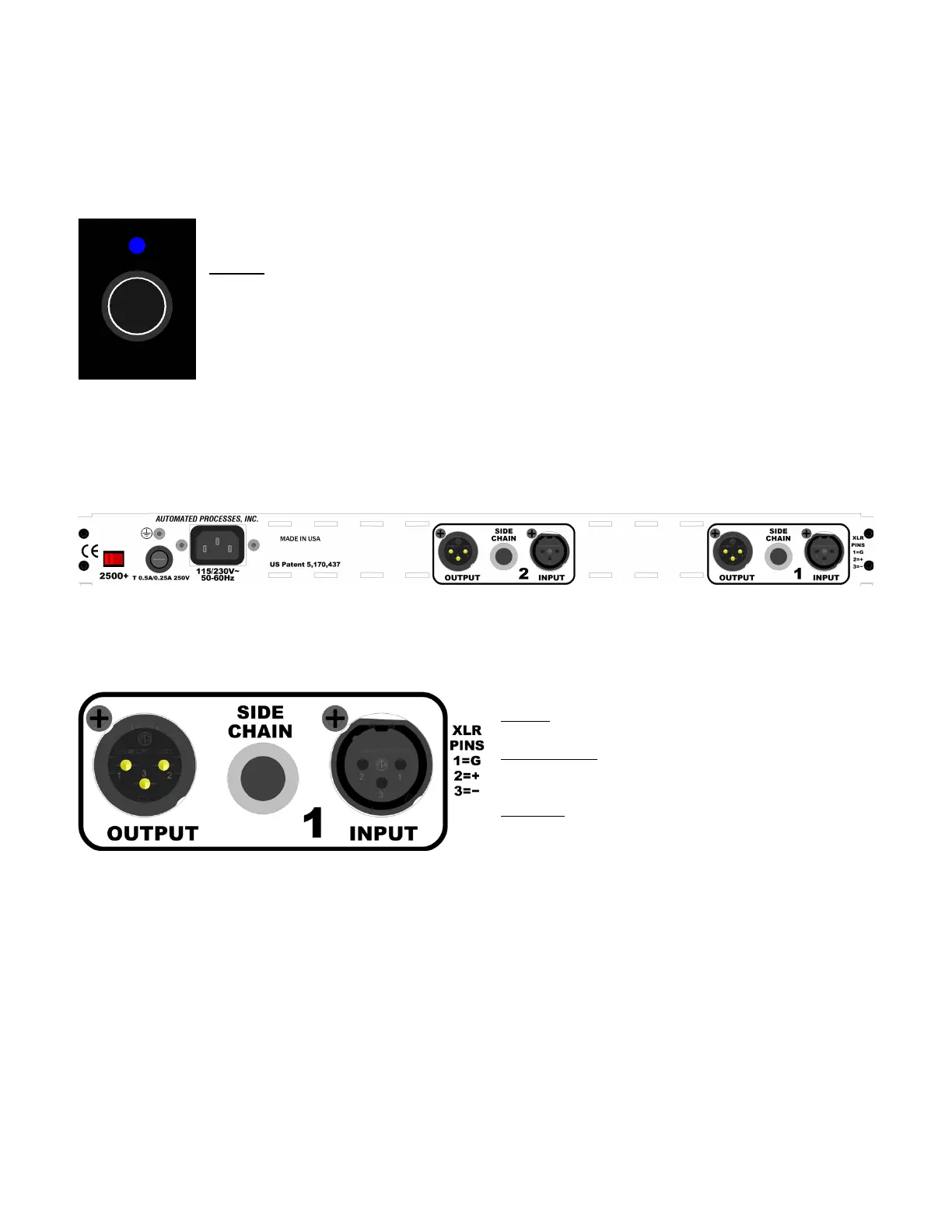
10.2 Rear Panel
The rear panel of the 2500+ provides the Left and Right audio input, output, and side chain
connections, as well as AC power connections, voltage selection, and fuse.
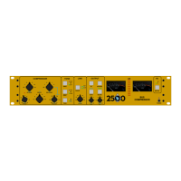
10.2.1 Audio Connections
Each audio channel, Left and Right, has an INPUT, OUTPUT, and SIDE CHAIN input connection.
INPUT: Balanced, line-level
• 3-pin female XLR connector
SIDE CHAIN: Balanced, line-level input
• ¼” TRS connector
• Tip=+, Ring=-, Sleeve=ground
OUTPUT: Balanced, line-level
• 3-pin male XLR connector
NOTE: Channel 1 = Left and Channel 2 = Right