7
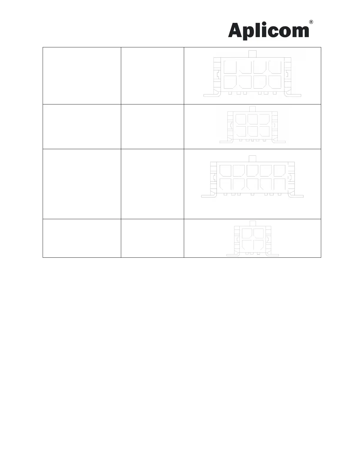
IO cable / IO 1/2
Pin 1, OC 1/2
Pin 2, Pulse 1/2
Pin 3, DIN 1/6
Pin 4, DIN 2/7
Pin 5, DIN 3/8
Pin 6, DIN 4/9
Pin 7, DIN 5/10
Pin 8, GND
Blue
Grey
Red
Yellow
Orange
Violet
Brown
Black
CAN cable / CAN
Pin 1, CAN_H1
Pin 2, CAN_L1
Pin 3, K-line
Pin 4, CAN_H2
Pin 5, CAN_L2
Yellow
Grey
Violet
Blue
Green
Black
Bus cable / BUSMIX
Pin 1, TXD5
Pin 2, RXD5
Pin 3, GND
Pin 4, RS485_A
Pin 5, RS485_B
Pin 6, GND
Pin 7, PWR OUT
Pin 8, GND
Pin 9. K-line
Pin 10, GND
Orange
Red
Black
Brown
Yellow
Black
White
Black
Green
Black
1-wire cable / 1-Wire
Pin 1, NC
Pin 2, 1-Wire PWR
Pin 3, 1-Wire Data
Pin 4, GND
Semoflex 3x0,25 mm²
Software configuration
Use standard micro USB cable
LEDs
Unit includes 6 LED indicators. Led’s A to D are under application SW control, led E shows modem and
power status and led F shows internal battery charger status.
Led E
Green – Unit is powered
Flashing orange with 50/50 ratio – modem is trying to connect network
Green with fast blinks – modem is connected to network
Led F
Orange – internal battery not connected, failure, over temp, under temp, over time
Red – internal battery is charging
Green – internal battery is charged
Testing installation
If the unit has a default configuration
1. Connect the power on.
2. Led B is red after start up and green when GPS fix is received (this takes about another 30s). Now the unit
is working correctly. If the unit has a service providers configuration follow their instruction, for example
ensure that data is sent to the server.
3. Leds A, C and D are not used
5 6 7 8
1 2 3 4 5
6 7 9 8 10
1 2 3
1 2
3 4