8. TAMPER PROTECTION
The Wireless Combination Smoke, Heat and Carbon Monoxide Detector has a built-
in tamper switch which will cause a tamper signal to be transmitted to the control
panel if the detector is removed from the mounting base. The detector also
includes an anti-tamper feature which prevents the detector being removed from
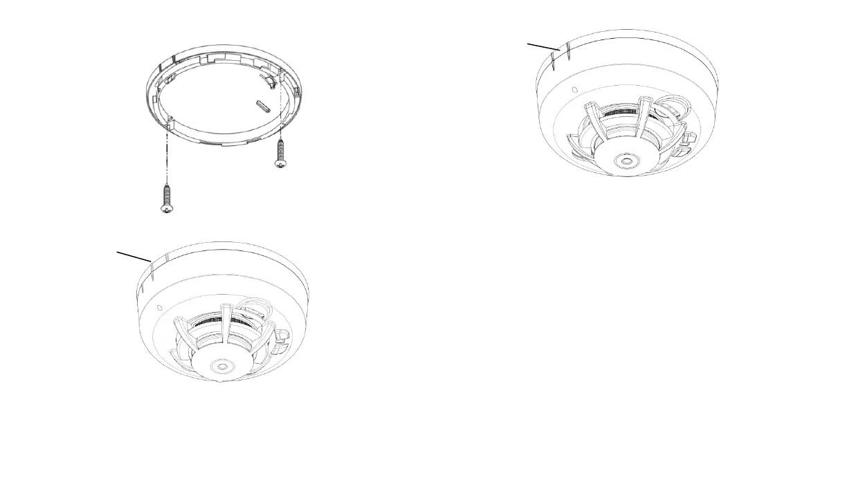
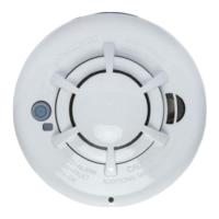
the mounting base. To enable the anti-tamper feature cut the anti-tamper tab on
the mounting base (Figure 16 and Figure 17) and install the detector on the
mounting base. When the anti-tamper feature has been enabled, to remove the
detector from the mounting base, a small screwdriver must be inserted in the anti-
tamper release hole (Figure 18) to press on the release lever whilst turning the
detector counterclockwise.